
|
|
|
#1
 09-05-2026, 09:42 AM
|
||||
|
||||
|
Sharp C-1410 no power (smps issue)
I received a Sharp C-1410ND a couple of days ago, it was working fine for about two hours with my Wii connected, I was getting some snacks when I came back to a dead TV. Didn't hear any unusual like a pop or crackle.
Opened it up to check if anything had gone fubar, but no sign of that. Plugged it in again, was met with a whine that started high in pitch and went down until it halted. I have uploaded a YouTube video with the sound of the power supply issue. The sound is coming from the power supply area. The issue is most likely in the switch mode power supply, I am suspecting the primary side. After reading up on these power supplies, I started troubleshooting. Started with checking for cracked solder joints and reflowed some suspicious ones. Checked the diodes, most of the resistors, capacitance and ESR of the electrolytic capacitors. Everything checked out fine. Checked the voltage on the main filter capacitor C706, got around 335V. On C710 i get 72V. Seems like resistor R709, R710 and R711 is the only thing getting hot on the board according to my thermal camera, around 35-50°C. They are marked in yellow here:  What could this issue be? It sounds like there is either something in the feedback circuit that has gone haywire. I only get about 15V for a brief moment on C635 on the secondary side, so something is happened. Maybe a short that kicks the PSU into overload? I have not checked the ceramic/film capacitors as they are usually okay, but might be worth a shot to check them too? The schematics for the TV is available on ElektroTanya. Appreciate the help. Last edited by ostlar; 09-05-2026 at 10:19 AM. 
|
|
#2
09-11-2026, 01:50 PM
|
||||
|
||||
|
After some more diagnosing I've concluded that there is something shorting out the secondary 115V side. That makes sense with the voltage rapidly dropping and the sound the power supply makes when it cuts into protection.
I measure 20,7 ohms over the 115V filter capacitor, it is not supposed to be that low. I have checked the filter capacitor C635 with an ESR meter and the over voltage protection diode D601 with a multimeter, both are okay. At 115V and 20,7 ohms, the power draw would be 5,5A or 632.5 watts, definitely not right. I realized that his has an identical chassis to my Sharp C-3700, so I've been using that as a reference if I find something suspicious. I have systematically measured most of the 115V circuit and followed wherever the resistance gets lower, and I am at 9,5 ohms at the lowest around the horizontal output transistor Q602. Removed the transistor and tested it, no issue there. I have also tested C618 that sits right by the HOT and is referenced to the ground. Here is a screenshot with my measurements, the numbers show resistance to ground measured over the component that references ground, mostly capacitors:  I have hit a dead end, can't seem to find any resistance lower than 9,5 ohms to the ground. I have tested most of the components that are referencing ground in the area with the lowest resistance. What am I missing? Could it be an internal short in the flyback? I hope not.
|
|
#3
09-11-2026, 04:03 PM
|
||||
|
||||
|
Quote:
Assuming those are okay, and that you have a low-resistance short, then it should be possible to isolate it by removing components and testing points to ground with those specific components out of circuit.
|
|
#4
09-11-2026, 06:52 PM
|
||||
|
||||
|
.
Hi! - You may not have a short, but instead you may have a problem related to one of the hold down circuits. Low voltage, or high voltage hold down circuit. You can see on the schematic there is a small winding off the flyback that goes to that 5 pin chip in the power supply. I think it's labeled Impulse, or Trigger. It's a safety circuit, and this problem is made for service with a Variac. Set it low and turn the set on and see if it fires up. Theory is the tv does not develop voltage high enough to trigger the hold down circuit, and you find the fault with a volt meter..... Keep in mind that if part of the tv does not start, with no load the B+ May run artificially high.... The other thing you can do is look at the tutorials on YT for this problem Search Sharp Hold Down Circuit Troubleshooting - or - similar. For some reason the Horiz Osc. is starting and shutting off. This tv must have been made before the Jungle IC. that controlled everything, because the hold down IC is stand alone by the power supply....... I don't remember ever having to work on a Sharp Hold Down Circuit before, so best I can offer is to look at the tutorials on YT, and do plenty of Google searches on the Sharp Hold Down Circuit tutorials as there seems to be a few on YT, so there may be some on G. This tv does not have a switching power supply, but does make some of the supply voltages off the flyback, A short lived design. In this video you can see he finds a bad cap, and talks about the Protection Circuit and appears to have full B+. So also search Sharp Protection Circuit maybe add your model number etc. https://www.youtube.com/watch?v=7CndoU7Qg-w ------------------- And in this video you can see he found a bad resistor near items labeled D604 which is in the Horiz Output area, Same numbering system as your set. Open resistor may let some voltages run high if in the feedback to the hold down circuit. https://www.youtube.com/watch?v=_Y4G1e7AZGY And again this title of the video is for the hold down circuit. --------------- Be sure to check the fusable resistors, and high value resistors, Diodes, and Zener Diodes as well, because a Zener diode can be used as a trigger. Hold Down circuits are very tricky....... .
__________________
Yes you can call me "Squirrel boy" Last edited by Username1; 09-11-2026 at 07:45 PM.
|
|
#5
09-22-2026, 10:46 AM
|
||||
|
||||
|
Thanks for the replies. On my other working TV with the exact same chassis, I get 20 kilo ohms on the 115V line on the secondary side, but on the non working TV I get 25 ohms.
This is definitely something shorting out, but I am not sure what. I've come to a dead end in around the HOT. Last edited by ostlar; 09-22-2026 at 10:53 AM.
|
| Audiokarma |
|
#6
09-22-2026, 03:27 PM
|
||||
|
||||
|
Quote:
I believe that is the hold down circuit around IC701 in your first image. I would start by comparing the pins on the broken one with the pins on the working one and see what that looks like. You can watch those YT vids that they linked about it for more info
|
|
#7
Yesterday, 07:50 AM
|
||||
|
||||
|
Quote:
Here is a possibility - Each color tv has a Degaussing circuit, it sends full power to a coil for the first second the tv is switched on, then a thermister gets hot, and it gets turned off gently. It's possible your "good tv" has had this circuit fail, and it reads open, while the other tv has a good Degaussing circuit and you read 25 ohms... Most often this is on a plug, you could try unplugging it and retest. The coil is around the picture tube. On the schematic it's near the AC plug at the bottom.... Second possibility - you have a problem with a circuit fault, nearly a short and it should be smoking or kicking a fuse..... 25 Ohms should be easy to find.... Are the probes in exactly the same spots including polarity when you measure this on both tvs? If it's not the degaussing circuit then you can unsolder components, and disconnect parts of the circuit and recheck resistance to find the 25 ohm section..... Also - check the other resistors next to the ones getting hot, R 701, - R707, They makeup a resistor network with a test point 18 I think it says... Pretty much anything around IC701..... Since you have a good tv as a reference, you may want to check resistances at critical points, and even voltages, like at IC 701, resistances at the flyback, Horiz. Output Transistor etc.... Keep in mind when checking resistance probe polarity is important, if the meter 'sees' a diode it will give a different reading in one direction, so remember to keep polarity the same when measuring from one tv to the other..... Also in one of those Hold Down Protection Circuit videos the guy finds a bad cap with a bulge on top, so keep your eyes open for stuff that don't look right.... .
__________________
Yes you can call me "Squirrel boy" Last edited by Username1; Yesterday at 08:30 AM.
|
|
#8
Yesterday, 10:25 AM
|
||||
|
||||
|
Thanks for the reply guys.
I have some good news and bad news. Did some more tinkering today and decided do unsolder the flyback, as it was the last component in around the low ohm area that I hadn't removed and tested. The good news is that the low resistance to ground disappeared when I removed the flyback. The bad news is that it is definitely something shorted in the flyback. Check the readings between the non working and working flyback:  I will have to do some research to find a replacement, it is marked: 6402 MSH1FCB04 F1442CE Seems like there are several available new on eBay from Australia for $50 including shipping and tax, not bad. Now my question is, could there have been something causing this short? I can't seem to find any obvious signs in the circuit now that the flyback is removed, everything seems to be in order.
|
|
#9
Yesterday, 10:33 AM
|
||||
|
||||
|
Here is the schematic of a replacement, HR 7756:
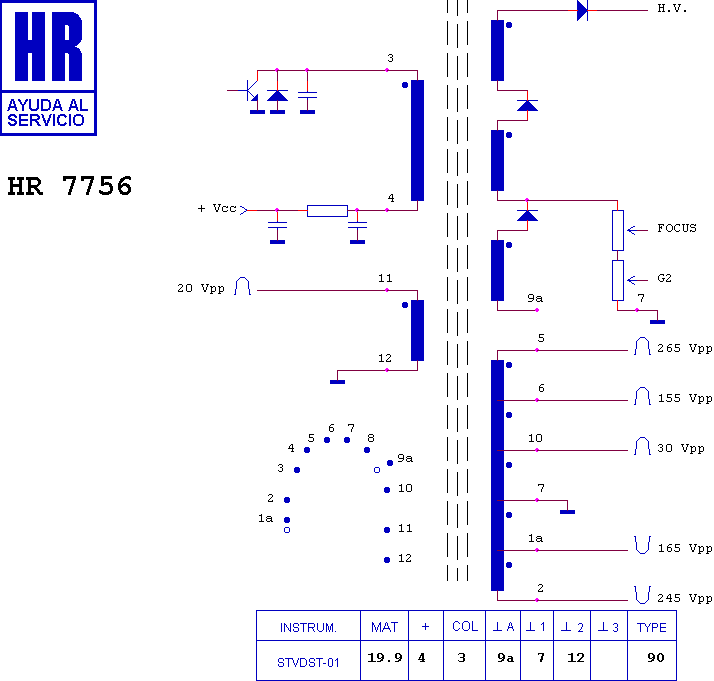 Pin 3 and 4 should be isolated from the other pins. The working flyback is tested in circuit, so the 20,3k ohms might be some other components, but there is a clear fault here.
|
|
#10
Yesterday, 02:32 PM
|
||||
|
||||
|
Quote:
Idk, Username1, do you have an explanation for it?
|
| Audiokarma |
|
#11
Yesterday, 06:59 PM
|
||||
|
||||
|
.
Good Evening..... Well Well.... I'm going to assume measurements are with reference to pin 1a. on the schematic of the replacement part, as it looks like it's the same as pin 1 on the tv schematic.... Anywho - I don't see why there would be any readings at all going from pin 1 to anything that is not directly connected to that winding..... I would assume measurements to be compared would be 3, & 4, - 11, & 12, - 5, to 6, 7 10, 1a, & 2. etc, within each winding. Then you can check each winding to another winding, like 3, to 11, to be sure there are no internal shorts, and do that with each set of windings.... Could be a big bunch of stuff to check.... Question - Are the numbers on the parts you are comparing from the 2 tv's exactly the same? If not that may be a reason for different readings..... Also there could be a short developing between windings 3, & 4, to any of the windings in the group of 2, 1a, 10, 6, & 5. Well, what to do..... You could take the transformer from the working set and put it in the non-working set and see if that fixes it.... But I think I would not put the one from the non working set into the one that is working...... just let the suspected bad part sit out for a while... I'm leaning towards you have a bad flyback....It's common on newer tv's like that... And pins 3, & 4 are the pins driven by the horiz output transistor, so that coil does a lot of work and would be that gets stressed the most... Good work, I put my money on the flyback..... Another question, what is the resistance from pin 3 to 4 on both of the 2 transformers? Are they close to the same? Anyway, 14 ohms from pin 3, & 4 to pin 1a on the set that does not work looks like a short to me...... I really can't explain the 20K on the working set unless it's from other stuff - I think it's still in the set right..? My money is still on the flyback being bad... Good Work. .
__________________
Yes you can call me "Squirrel boy" Last edited by Username1; Yesterday at 07:10 PM.
|
|
#12
Yesterday, 11:48 PM
|
||||
|
||||
|
Quote:
The "working" flyback must still be in the set, or it's also started to go bad maybe. Could be a common failure mode?
|
 |
|
|


 Linear Mode

