
|
|
|
#16
 07-25-2021, 08:51 PM
|
||||
|
||||
|
Questions 1 and 2. If you have the back open change those white caps! They can fail at the drop of a hat even if they test good, and when they fail they spray conductive foil everywhere that can short other stuff and increase collateral damage.
You can buy the spade end crimp connectors from any hardware store. What I'd do is strip the one wire and solder on a crimp connector. Last question. Most makes used the same cathodes for everything from 5" to 27" CRTs. That cathode has a limited amount of electrons it can emit. The bigger the screen the more emission it needs for a given brightness level, thus smaller CRTs last longer and can work better with a weak CRT.
__________________
Tom C. Zenith: The quality stays in EVEN after the name falls off! What I want. --> http://www.videokarma.org/showpost.p...62&postcount=4 
|
|
#17
07-25-2021, 11:57 PM
|
|||
|
|||
|
Quote:
I went ahead and replaced all of the vacuum tubes (except the CRT), with new old stock tubes. However, I was not able to replace the ultor rectifier in the high voltage cage, because the top cap was very tight and I worried I might damage it when removing it. This is my first tube based ultor rectifier. Question #8: Any tips for removing the top cap without damaging it?  I also cleaned the glass on the triode section of the CRT, so you can now see inside it. It is a very large electron gun for such a small CRT. Its circumference is as big as the horizontal output tube, which is also a very wide vacuum tube.
|
|
#18
08-15-2021, 06:58 PM
|
|||
|
|||
|
I got around to replacing the white axial paper dielectric film capacitors that are known to explode. In the HC chassis, these are capacitors: C44, C67, and C105. However, in some HC chassis builds, such as my TV here, C44 is not a white axial capacitor, but instead is a much more reliable "orange drop" polyester dielectric film capacitor. Capacitors C67 and C105 are located in the back of the chassis on the left corner near the knob for horizontal hold. In order to try to match the "look" of the original white axial capacitors, I went with white axial Cornell Dubilier brand metallized polypropylene film capacitors.
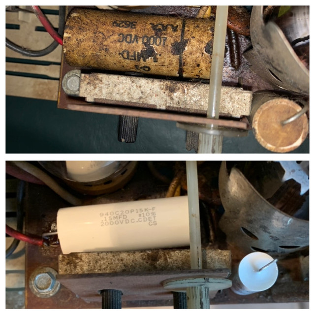 Picture: top is before, bottom is after Capacitor C67 This capacitor is a decoupling/filter capacitor for the 670V boosted B+ power supply. It has to be able to tolerate 15khz ripple, and it sits right next to the power amplifier tube for horizontal sweep, so it has to tolerate lots of heat! The original capacitor is a paper in oil dielectric, and the 15khz ripple and the intense heat from the power amplifier tube slowly boil the oil out of the capacitor. This causes the dielectric's voltage rating to decrease bit by bit until the capacitor fails with a 400 volt short circuit. A proper replacement should have a self-healing dielectric material that has a higher temperature rating. Also, the capacitor should have a smaller diameter, as the original capacitor's 20mm diameter has the capacitor almost touching the power amplifier tube's glass! Every millimeter smaller the diameter, the less heat transfer from the nearby vacuum tube. A higher voltage rating will also prolong life. Film capacitors have a life expectancy that is exponential in the magnitude of voltage derating. Finally, a 50% increase in capacitance for this capacitor will make the capacitor more effective at reducing ripple voltage (see before vs after below), without resulting in excessive surge current during the initial charging of the capacitor. Before vs After:
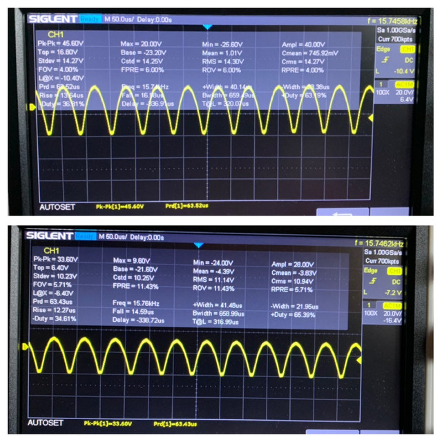 Picture: oscope of "Boosted B+ Voltage" top is before, bottom is after Capacitor C105 This capacitor is a decoupling/filter capacitor for the B+ power supply. It is in parallel with capacitor C2, a 100 mfd electrolytic capacitor, but since the ESR of electrolytic capacitors is so high, they are only effective at reducing low frequency ripple such as rectified power outlet ripple of 60hz or 120hz. For TV and radio frequency ripple, a very low ESR capacitor is required. Increasing the capacitance by about 10x will more effectively reduce the high frequency ripple, and does not increase the surge current during power on to an unsafe level. Before vs After:
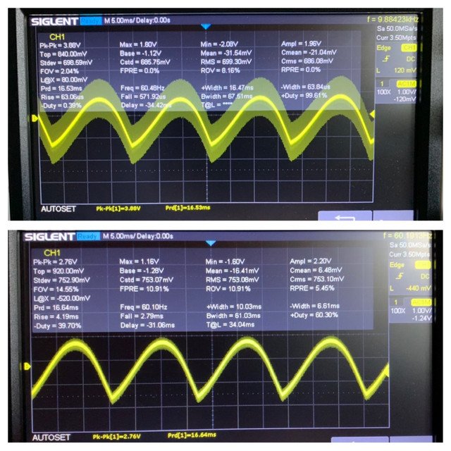 Picture: oscope of "B+ Voltage" top is before, bottom is after Last edited by LukeSimon; 11-11-2021 at 02:11 PM.
|
 |
|
|


 Linear Mode

