
|
|
|
|
|
#1
 10-22-2011, 12:30 AM
|
||||
|
||||
|
Columns of dashed lines that extend down into the picture are definitely copy protection. Here's a wicked case, shown on my 1961 CTC-11.
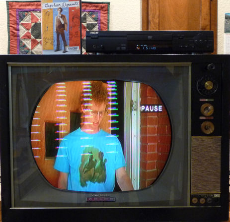 Google for "video stabilizer" to find inexpensive devices that will let you play your copy-protected DVDs on your old TVs without this annoying hash. Different TVs respond differently to this stuff, and I imagine there are different copy protection schemes. In any case, the stabilizer lets me play any of my DVDs on any of my old TVs. This is different than the other two hash sources mentioned (the thin horizontal row of dashed junk at the extreme top, and the widely spaced diagonal lines). Phil Nelson Phil's Old Radios http://antiqueradio.org/index.html 
|
|
#2
10-22-2011, 10:41 AM
|
||||
|
||||
|
I messed around with adding retrace blanking to my Admiral 20B1, the thread talking about it is here: http://www.videokarma.org/showthread...hlight=admiral
|
|
#3
10-22-2011, 05:25 PM
|
||||
|
||||
|
All the capacitors in the set are new.
It seems that #1 is OK, and is to be expected. That's fine, as if it is normal I'm OK with it. I just wanted to make sure I didn't mis-connect something. I was given a DTV converter and today I picked up an amplified antenna as well as an RF interference trap. I wanted to compare "broadcast" TV vs DVD and VCR signals. My setup is as follows: I have the antenna hooked up to the DTV converter via coaxial cable, which is then connected to the "IN" on the VCR. The DVD is connected to the VCR so the VCR acts as the RF modulator. The VCR is connected via coax to the RF interference trap, and then to a 75 ohm coaxial to 300 ohm dipole converter. I also temporarily reconnected the removed circuitry to see how it effected the retrace lines. The retrace lines still show up no matter the video source, but the added circuit seemed to diminish them. I can live with them for now, knowing they are normal for an Admiral set, and I am able to tune them out most of the way. The big issue I need to address now is the excessive width of the raster. The height I can adjust with no problems, and I have the picture somewhat better centered on the screen. It extends approximately a half-inch beyond the widest point of the CRT. The tube mask is only about 8" wide, so when the chassis is installed in the cabinet a lot of the picture is chopped off. I have a feeling if I can get the width down to the correct level, the linearity control will have a better effect. Last edited by UberVacTuber; 10-22-2011 at 05:40 PM.
|
|
#4
10-23-2011, 01:14 PM
|
||||
|
||||
|
That second circuit up there ^ is basically what I did on my 20B1. I understand why you need a positive pulse if you connect to the CRT grid, and negative pulse on the cathode. But I notice that on the first page of that book posted, it says also to connect to whichever (grid or cathode) the video does not. I think I've had it work both ways (connected to the same place as the video, or the brightness control), so what is the reason for this?
|
|
#5
10-23-2011, 11:27 PM
|
||||
|
||||
|
Quote:
I was able to download the 30A1 schematic from the ETF website. It looks like the 6K6 vertical output is transformer coupled to the vertical yoke windings, rather than directly coupled using an autoformer. So as the book points out, that ends up making the pulse negative on the yoke side of the transformer. I’m not sure where the proper place is to pick off the positive going blanking pulse on this set. Possibly directly off the plate of the 6K6 vertical output, but it may need to be divided down to a lower level. I’m just not experienced enough to say exactly what will work. Last edited by Kevin Kuehn; 10-23-2011 at 11:30 PM.
|
| Audiokarma |
 |
|
|


 Hybrid Mode
