
|
|
|
#16
 10-06-2011, 10:09 AM
|
||||
|
||||
|
You want to get the oscillator speed down as quickly/easily as possible to see what else is going on,if I remember right I think it's possible to adjust L14 and that moves the frequency,have a look and see if you can (may be wax in the thing securing the core) and try 2 turns of the core in and note the effect and then go the other way if not right.
I just found my Sams manual on the TV,C99,C100 and C101 were certainly changed.Never had a problem with the sync diodes but type shouldn't be too critical. It can be frustrating working on this TV...... On weak signals or with contrast low the sync can be be weak which is maybe what you're seeing.I block changed most of the electrolytics caps in the set,certainly if any linearity/height problems go straight for the ones below the height/linearity presets. Youtube video of it here http://www.youtube.com/watch?v=StbCuBM3lA0 Good Luck Hugh Last edited by Mr Hoover; 10-06-2011 at 10:19 AM. 
|
|
#17
10-06-2011, 04:59 PM
|
||||
|
||||
|
Thanks, I found a new electronics store today and came home with a little sack of caps to try.
I have been using a weak signal, broadcasting from the modulator on the far side of the house. It will be easy enough to hook up a signal generator or DVD player and see whether signal strength matters. A static test pattern may make it easier to see what's happening, too. I will try to find time to change C98/C99/C100/C101 sometime later today. Phil Nelson
|
|
#18
10-06-2011, 07:22 PM
|
||||
|
||||
|
Quote:
__________________

|
|
#19
10-06-2011, 10:25 PM
|
||||
|
||||
|
___brief thread interrupt-germanium diodes are useful with some evp experiments.the diode method for some reason works best with germanium types.
___back to your program
|
|
#20
10-06-2011, 10:26 PM
|
||||
|
||||
|
Quote:
Do you have a scope to check the waveforms? This circuit wants the approx 5 volt pp waveforms shown on the schematic. As stated above, L14 should affect the frequency. The oscillator is controlled by the voltage that is generated by the two detector diodes and filtered by R108, R109, C36, C99. R4 sets the center voltage on the detector when the frequency is correct. If there is no setup procedure, I suggest setting R4 and R10 to mid range, and then see if you can get the right frequency by tuning L14. However, optimum might be with L14 tuned slightly to one side of center and R4 adjusted to compensate.
|
| Audiokarma |
|
#21
10-06-2011, 11:04 PM
|
||||
|
||||
|
Wahoo!
 I think replacing C100/C101 turned the tide, although I replaced some other not-very-related caps in the same session. You can tell from the snowy picture that the signal in my shop is weak. Even newer TVs look snowy, and there's lots of interference from CFL bulbs, wall warts, & whatnot. I do have a scope, and it would be interesting to use it on this TV, but that's impractical given its construction. When put together so you can power it up, it's basically a brick. The boards are stacked so that only their edges are accessible. 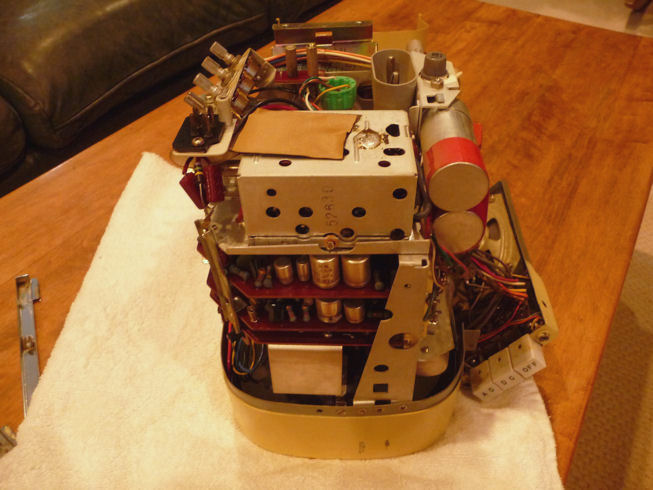 Anyhow, it looks like I'm on the right track. Both horizontal and vertical seem very stable. I'll play it for a while using different sources, to see how it holds up, before I decide whether it needs more new caps. I may replace a few more regardless, since I bought more today and rarely work on these new-fangled low-voltage gizmos. Thanks for the advice & encouragement. Phil Nelson Phil's Old Radios http://antiqueradio.org/index.html
|
|
#22
10-06-2011, 11:12 PM
|
||||
|
||||
|
Congrats! great picture
|
|
#23
10-07-2011, 02:06 AM
|
||||
|
||||
|
I couldn't resist quickly hooking up a pattern generator. Had to turn the gain way down, as its signal is strong.
 The screen geometry isn't too bad. Not sure what's going on with that warp on the far right edge. This set has almost no horizontal adjusters, so I may just live with it. In addition to vertical height and linearity, it has an adjuster (R5) called vertical bias. Anyone know its purpose? I don't see any mention in the manual, and I don't recall anything like that in old tube TVs. Incidentally, I was wrong about it being impossible to access the boards while powered up. The alignment instructions in Sams say that you can pull either the rear or center board, unscrew its socket(s), slide the socket(s) out through the mounting hole(s), and then plug the board back in. Presumably there is enough cable slack on the sockets to enable this. I may try it tomorrow, just to see if it works. For the record, the manual also gives a procedure for setting the horizontal frequency, first adjusting the stabilizer slug B1 and then the horizontal frequency control as I was doing in the first photo. Amazing what you can learn when you slow down long enough to read the manual. (When I was a technical writer, we had an acronym RTFM, which I won't decode here.) Possibly, I could have tried this in the first place and avoided replacing so many parts, but that wouldn't have been half as much fun  Phil Nelson
|
|
#24
10-07-2011, 06:04 AM
|
||||
|
||||
|
Good to see the TV is working !.
I can see some stretch on the left hand side,compression in the middle and a bit of stretch on the right side,horizontal linearity isn't so good on these TV's.There's the adjuster preset on the other side of the chassis tied in with the horizontal output transistor to slightly vary,may help,look in the manual and see if it recommends what to do with it.Not seen the warp effect on the right side before. Your vertical linearity looks good,adjusting that preset you mention gives a non lin effect in the middle of the vertical scan I think,think best to leave alone looking at your picture now! Make sure the 2SC41 horizontal op transistor isn't running too hot,the heatsink should be gently warm to touch and not roasting after say 20 minutes.Some early versions of that transistor tended to get very hot,for one of my 8 301's I took one out of a scrap later 9" set and it ran much cooler. I think some of those connectors on the chassis underneath have short ground wires,may be wrong. Hugh
|
|
#25
10-07-2011, 08:45 AM
|
||||
|
||||
|
Yah, the horizontal linearity is currently stretched somewhat on both margins, not on one side alone as I often see in older sets. The manual doesn't say a lot about horizontal adjustments, just telling you to use the stabilizer slug and frequency control to achieve lock, and then:
"Adjust Horizontal Drive control for best linearity. Repeat adjustments if necessary." When I was fooling around with adjusters before reading that part, I found the Drive control and tried using it in the customary way, adjusting until you see a light drive line and then backing off a little. A drive line never appeared, but I noticed that the Drive control changed horizontal centering, so I centered the picture for the time being and left it at that. I will check the temperature on the 2SC41 transistor as you suggest. I can also check its voltages shown on the schematic if that section is accessible when the center board is removed. I'm curious about that whole board-pulling scheme. If you really can power up the TV with one board or the other pulled out, that would be good to know for future reference. Phil Nelson
|
| Audiokarma |
|
#26
10-07-2011, 10:05 AM
|
||||
|
||||
|
The drive control alters the width a little bit I found.
Some sets have extra small value HV caps fitted across the horizontal scan coil wires where they plug into the board,they alter the width... I think you can see why they dumped the model quickly and went onto the the little 5" set. While you're measuring volts I had problems with low volts for the video amplifier supply which is rectified from the horizontal op stage,changing the diode for a modern type fixed it. The diode is near the transformer at the top of the board,you can just about get to it to measure with the board in place I think,or check on the video amp which is on the middle board near the top. Hugh Last edited by Mr Hoover; 10-07-2011 at 10:13 AM.
|
|
#27
10-07-2011, 10:39 AM
|
||||
|
||||
|
Me no unnerstand a lot of the technical stuff y'all are talkin' here, but it seems that this set came by the nickname "Sony's Fragile Baby" honest...(grin)
__________________
Benevolent Despot
|
|
#28
10-07-2011, 07:12 PM
|
||||
|
||||
|
Congrats - The noisy pic looks stable, so I think there's no more to do regarding sync.
The stretching of both sides of the H sweep is usually a design issue, depending on choice of components in the horizontal sweep section. Some sets have a deliberate "S-correction" built in that shapes the horizontal yoke current to reduce the scan a bit near the edges, but this one may not. There is no adjustment for it even if it's built in.
|
|
#29
10-08-2011, 01:01 AM
|
||||
|
||||
|
I went ahead and replaced the rest of the small electrolytics. It makes a decent picture now. This is from a test pattern DVD:
  This TV is extremely sensitive to signal strength, making me wonder if there's something funky with the AGC. The gain control is very reactive, and I may need to adjust the gain when switching from one DVD to another, not to mention switching from one source to another. The warp on the right margin is worst with a white-background scene like this. It was not apparent at all, and the width was more than adequate, when I played a DVD of Gone With the Wind on the same player. The vertical hold is not as stable as I expected. Not awful, but not great, either. It also has a noticeable hum, even with volume turned all the way down. This is not your typical intercarrier buzz, although I cautiously adjusted the ratio detector secondary (A9) as directed in the manual. The TV is watchable in this state. Perhaps some of these nits are just in the nature of the beast. I don't want to flog it trying to squeeze BMW performance from a Chevette, but I want to improve the vertical hold, at least, before quitting. Phil Nelson
|
|
#30
10-08-2011, 01:30 AM
|
||||
|
||||
|
Hi
There isn't any AGC on this TV I think,that's why it has this gain control and is critical in adjustment.The Philco Safari is the same,though has a 3 position sensitivity control,it seemd only the "second genration" transistor sets had something as exotic as AGC. "Contrast" is preset on the middle board with that little control,so sort of set that for best looking picture when happy with the gain setting...yes this set is a weirdo!!! The gain control is a dual ganged pot,one part attenuating the antenna signal and the other the IF gain.I found it was better connecting the antenna in at full gain all the time into the tuner,or one could end up with a slightly grainy pic but the IF gain about right,just resolder the coax inner going to the tuner to the top end of the pot where the signal is coming in via the same thin coax. Try running the TV from a 12 volt supply if you can and see if the hum goes and what happens to the picture bending effect on the right side.If you haven't the right DC sony connector brown wires in the TV are the 12 volt line I'm fairly sure. Around the sync separator stage there's a 100K resistor which wasn't fitted on the pcb on one of mine,holes there but never been soldered in...fitting that cured sync problems that set had. You're getting there... Hugh Last edited by Mr Hoover; 10-08-2011 at 06:55 AM.
|
| Audiokarma |
 |
|
|


 Linear Mode

