
|
|
|
#16
 09-12-2010, 03:25 PM
|
||||
|
||||
|
Pix 4, (closeup of the HV connector) shows a label...looks like 21ACP4A. I don't see an ion trap installed on the tube, so I suspect the "SG" prefix stands for "straight gun", and no ion trap is needed.
jr Last edited by jr_tech; 09-12-2010 at 03:40 PM. Reason: add link to pix 
|
|
#17
09-12-2010, 03:42 PM
|
||||
|
||||
|
I saw a label on the tube saying no ion trap was needed. I have a Sencore tube tester somewhere, just need to find it. I don't think it can specifically test CRTs.
Know of a good source for another tube base? Using a little PB Blaster and some careful prying I got the connector off the base without damage. One wire in the base is still hanging on, so indexing the pins shouldn't be an issue later on. I spent some time cleaning things up. Yes, I was careful not to scrub the makings off of the tubes. I have a friend who repairs Hammond organs who warned me about that. I have a great picture of a box of tubes from his Novachord as my desktop background, shoot me a PM and I can email it to you. The insides cleaned up very nicely. It needs repairs to the plastic volume knob, it doesn't grip the pot at all (the metal spring part is missing). Once I get the tube base repaired I'll see if the set works! I figured I would have to mechanically clean the PCB, but compressed air alone did the trick. -J Last edited by compu_85; 09-12-2010 at 03:49 PM.
|
|
#18
09-12-2010, 03:44 PM
|
|||
|
|||
|
Sadly I do not have any that would sub to this. It sure seems when they hit the mid 50's the number of different types sure expanded alot.
|
|
#19
09-12-2010, 03:48 PM
|
|||
|
|||
|
I think you could mark which one goes to which pin. Then use a soldering gun and heat it up and pull the cap totally off. Then heat each pin up, give it a smack to clean out the solder in each. then you are all set to solder it back on. The one time I did this I used some silicone and then after it dried I put some electrical tape on for further strength. I am sure there is something better tho.
|
|
#20
09-12-2010, 03:52 PM
|
||||
|
||||
|
My only worry is that so little of the base is left I don't know if it will be mechanically stable. Almost half of the part which would be glued to the tube is gone. I'd hate to have a wire snap off at the glass because the connector wiggled around too much.
Then again, there's very little weight hanging off the connector. Reading through things it seems people like using silicone to re-attach these. Has anyone ever tried JBWeld? I'd think that would make for a more stable bond.
|
| Audiokarma |
|
#21
09-12-2010, 04:18 PM
|
||||
|
||||
|
Quote:
 Sometimes people rob the bases off of old CRT brighteners, such as this: http://cgi.ebay.com/TELEMATIC-CRT-BR...item20b389a528 Not affiliated with the sale, jr Last edited by jr_tech; 09-12-2010 at 04:34 PM.
|
|
#22
09-12-2010, 09:55 PM
|
||||
|
||||
|
Nice Avatar!!! Do you have a Lisa?
|
|
#24
09-12-2010, 10:19 PM
|
|||
|
|||
|
Quote:
Sorry, off topic.
|
|
#25
09-12-2010, 11:41 PM
|
||||
|
||||
|
Be careful using compressed air! Low(er) pressure is just fine for blowing out all that dust and won't tear apart components and labels!
Nice set! At least the neck didn't get busted and gone to air.
|
| Audiokarma |
|
#26
09-13-2010, 12:42 AM
|
||||
|
||||
|
Just be very careful with the wires coming out of the tube base, they will break easily if bent too much.
Most of these should have five wires coming out of the tube, maybe six if it's electrostatically focused but I don't think they were that late. I think they go in to the cap in the same order they come out of the tube, in any case the heater wires should go one on each side of the index key.
|
|
#27
09-13-2010, 01:18 AM
|
||||
|
||||
|
Yes, I have a Lisa 2/10 with lots of other goodies, including a working internal disk
 But that's a story for another day. It needs some electronic restoration of its own, I'll probably detail that here when I get to that project. But that's a story for another day. It needs some electronic restoration of its own, I'll probably detail that here when I get to that project.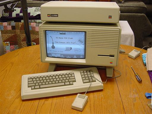 Looking at the picture tube all 5 thin wires go in order. I'll pick up one of those brighteners to thief the connector off. Unless someone has an old crappy one they want to sell me  I hate to tear up something NOS. I hate to tear up something NOS. Oddly enough I don't think the pilot light in the tuner dial was ever hooked up on this set. There's no lamp in the socket, and the wires for it are not hooked to anything, but were not cut off: They have a short portion stripped and tinned at the end. -J
|
|
#28
09-13-2010, 10:04 AM
|
|||
|
|||
|
I wouldn't worry about getting another base for the CRT. With the bakelite broken away like that it's a lot easier to line up the leads. Lay the set on it's face to resolder pins.
|
|
#29
09-13-2010, 11:10 AM
|
|||
|
|||
|
General Electric CRT
General Electric built very good CRT's and I'll bet this one is in good shape, as late as it is.
You can fix that socket ! Pallophotophone
|
|
#30
09-21-2010, 11:12 PM
|
||||
|
||||
|
Built a dim bulb tester and got the tube socket repaired.
Tester with a soldering iron plugged in: Banderson suggested soldering fine wires to the tube leads. I did that. I used some epoxy to re-attach the tube base. I think it will hold together as long as the connector is removed carefully. I optimistically set up a mirror and flipped the switch! Sadly the set doesn't do very much. The tubes warm up, but there's no picture, no scanning sound, and no static on the speaker. I happened to get a phone call while the set was on and I did hear the "ba da da da da da" sound out of the speakers, so something in the audio stage is doing something. I looked at the bottom of the chassis and everything looks totally original. Time to start the troubleshooting tree, though I'm betting it's capacitors. -J Last edited by compu_85; 02-19-2011 at 12:07 AM.
|
| Audiokarma |
 |
|
|


 Linear Mode

