
|
|
|
|
|
#1
 07-27-2021, 04:25 PM
|
|||
|
|||
|
Quote:
I have a theory as to why high voltage focus became more popular than low voltage focus. The high voltage focus has both a lensing effect to focus the cathode ray into a tighter beam, AND it also has an acceleration effect due to a high increase in voltage in the direction leading towards the face of the CRT. The faster electrons move towards the face of the CRT, the less time they have to spread outwards from the center of the cathode ray. This, btw, is one reason why a low ultor voltage causes the picture to be blurry compared to a high ultor voltage. Less acceleration from the ultor anode gives the electrons more time to spread out. The low voltage focus designs, assuming they are a true Einzel lens, only focus the cathode ray, they do not change its acceleration along the axis perpendicular to the face of the CRT like a high voltage focus design does. This theory would help explain why low voltage focus CRTs had a reputation of being both less sharp than high voltage focus CRTs AND a reputation for not aging as well when it comes to losing ability to focus a sharp picture. Side note: vintage television is fun because it gives you an excuse to play around with a particle accelerator. Yes, a CRT meets the scientific definition of a particle accelerator. 

|
|
#2
07-27-2021, 08:13 PM
|
|||
|
|||
|
I spent a few hours reading research papers, articles, and patents on electrostatic lensing and especially on Einzel lenses (commonly referred to as low voltage focus) and bi-potential lenses (commonly referred to as high voltage focus).
First, the National Valve museum has scanned a great series of articles from 1950s thru 1960s that explain the basic nature of electrostatic lensing. The physical phenomenon is explained in this figure which shows the cross section of two conductors shaped as hollow cylinders with a vacuum gap between the two cylinders: 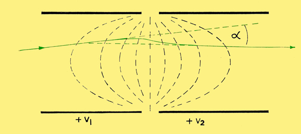 Whenever two cylinders are arranged in this manner and the difference in voltage between the two is non-zero, an electrostatic field is created as depicted by the equipotential lines. The lens is formed in the gap between the two cylinders, and its effect on the path of a cathode ray (green line) is analogous to the effect that a glass lens has on the path of a ray of light. The power of the lens corresponds to the magnitude of the difference in the voltage of the two adjacent cylinders. This patent from Intel has a great one page introduction on different CRT focusing designs. It also describes how to use the G1 anode as an iris: Quote:
 The patent goes on to describe a standard low voltage Einzel lens using the following diagram. Cylinder 20 in the figure is what televisions connect to the "focus" voltage. Cylinders 16 and 22 are connected via jumper 24 so they both have the same voltage, and they are then connected to the ultor anode using snubber springs 30. The gap between cylinder 16 and 20 forms a lens, and the gap between cylinder 20 and 22 also forms an identical power and shaped lens. This brings me back to the goal of maximizing the sharpness of the GE Portacolor. According to Einzel lens theory, the following DC bias settings will create the smallest iris opening and maximize the power of each electrostatic lens:
This voltage setting will likely have black levels that are incorrect. So starting from those "max lens power" voltages, if brightness is too high, I will lower G2 voltage until brightness is correct. Otherwise, if brightness is too low, I will raise G1 until brightness is correct. The electrostatic lens theory stats that as lens power is increased, spherical aberration is also increased. This is why increasing the G3 focus voltage above ground potential may be necessary for maximal sharpness. So the final step for calibrating the GE Portacolor's sharpness is to, starting at zero volts, increase the voltage of the G3 anode until the picture has maximal sharpness. Doing this will require modifying the GE Portacolor to add 2 additional pots. One for controlling red G1 voltage, and the other for controlling the G3 focus voltage. 
Last edited by LukeSimon; 07-28-2021 at 12:52 PM.
|
 |
| Thread Tools | |
| Display Modes | |
|
|


 Hybrid Mode
