
|
|
|
|
|
#1
 06-22-2018, 12:57 PM |
||||
|
||||
|
Ah, another forehead-slap moment. Lower resistance means lower wattage, duh.
I reviewed the photos that I took while experimenting, and it's clear that increasing the resistance stretches the left half of the image, while decreasing resistance squeezes the left half. Changing the resistance also changes the overall width somewhat. And it does not really cure the non-linearity I'm seeing. The far left edge is still squeezed, etc. And there is an additional variable -- the value of the .22 cap added to increase the overall width. Finding the best setting looks like a very iterative process: -- Try new resistor value -- Adjust the width, horizontal linearity, and horizontal drive controls for best linearity -- Try another resistor value -- Adjust all the etc. -- Repeat, repeat (maybe also adjusting the value of the .22 width-coil cap to see how that effects everything) That would be simpler with a direct-view TV, which you could plop onto the workbench and easily view while adjusting. Not so much fun when you are crouching on the floor to make adjustments and peering around to view the results in a little serviceman's mirror on the other side of the cabinet. OK, enough whining already! I hope to make some progress this weekend. Phil Nelson Quote:
Last edited by Phil Nelson; 06-22-2018 at 03:38 PM. 
|
|
#2
06-22-2018, 03:35 PM
|
||||
|
||||
|
Quote:
*My college only stocked 1/2W resistors so when the maths for a circuit design called for a 10W+ resistor that needed to last 30min of various measurements and tests without burning up we had to get creative with series-parallel combos to get a safe wattage...And the professors and parts room folks always wondered why there were so many off tolerance resistors in stock.  What kind of connectors does the main chassis use to hook into the cabinet projection system?... If it is just a set of octal and or Fat-pin tube base/socket connectors (and maybe a CRT socket/HV lead) why not make 5'-12' extender cables so you can keep the cabinet next to the bench and have the chassis on the bench connected to the cabinet for easy adjustment and testing....I did just that when I was working on my 21CT55 to make things easier for me.
__________________
Tom C. Zenith: The quality stays in EVEN after the name falls off! What I want. --> http://www.videokarma.org/showpost.p...62&postcount=4 Last edited by Electronic M; 06-22-2018 at 03:43 PM.
|
|
#3
06-22-2018, 11:15 PM
|
||||
|
||||
|
Extender cables would be handy, although not super-easy.
Two of the three cables would be do-able. The yoke connector is 9-pin, roughly the size of an octal socket with a ninth pin near the center. A second cable goes to the HV power chassis with a 4-pin connector. I don't have such connectors on hand, but I suppose you could scrounge them somewhere. The CRT cable looks tricky. It uses a funky 5-pin connector of a type I haven't seen before. The cup has terminals on the inside and it slides over the butt end of the CRT, which has little metal tabs around its edge. 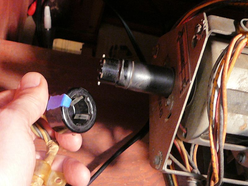 Weird,wild stuff, as Johnny Carson used to say. You wouldn't need an extender for the HV cable to the CRT second anode, since that doesn't come from the main chassis. It only goes between the two boxes of the Protelgram unit (HV power chassis and optical box holding the CRT). Phil Nelson Phil's Old Radios https://antiqueradio.org/index.html
|
 |
| Thread Tools | |
| Display Modes | |
|
|


 Hybrid Mode

