Quote:
Originally Posted by Phil Nelson

The article tells you to connect the heater connection to pin 4 of the adaptor socket. That's clear, but I want to make sure I understand the way they drew the heater connections in the preamp schematic:
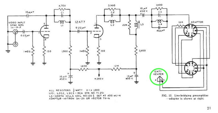
The drawing seems to show pin 4 of the adaptor connecting to pin 9 (the center tap) of the 12AT7. And pin 5 appears to be jumpered to pin 4.
Or am I reading the schematic incorrectly?
(The ground connection for the heater is made through pin 5 of the 6CL6 1st video amp tube, whose socket the adaptor plugs into. |
Looks ok to me... remember that the 12AT7 actually has two 6.3V heaters (one for each triode). They are wired in series between pins 4 and 5. If you used just those two pins, you would need to apply 12.6 V to light up the heaters. Pin 9 is the center tap between the two heaters... by connecting pins 4 and 5 together and applying voltage to that connection and pin 9, only 6.3 V is required, as the two heaters are then wired in parallel.
What could be missing on the schematic is the connection from ground of the TV to the ground of the added preamp... IMHO, the wire from pin 5 of the 6CL6 socket should also be connected to ground(s) of the preamp.
jr

 08-08-2015, 03:33 PM


 Threaded Mode
