
|
|
|
|
|
#1
 05-01-2015, 08:51 AM
|
||||
|
||||
|
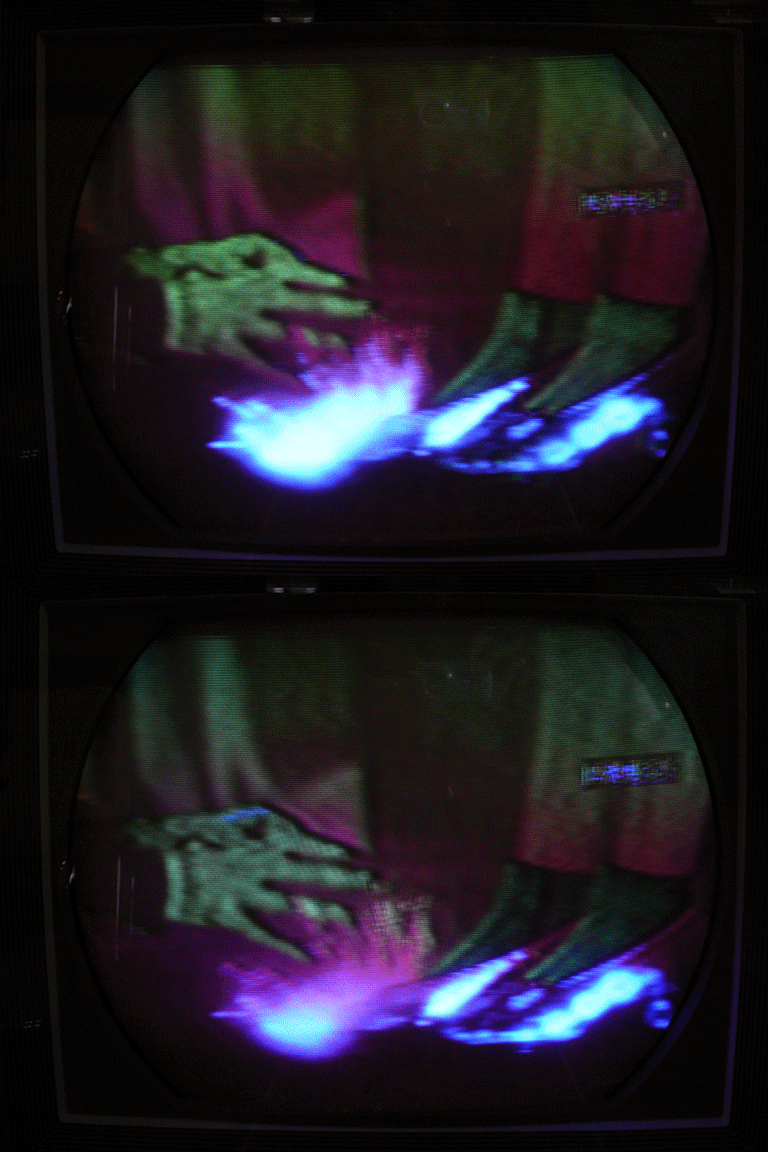
Bravo!! That must be very satisfying. That set has proven to be a tough dog and I bet you're learning a lot from it. I'm sure it won't be long now before we see a gorgeous screen shot of Dorothy
 -Clark 
|
|
#2
05-01-2015, 10:21 AM
|
|||
|
|||
|
Great work Phil! (Looking for a clapping-hand smiley)
 What does some reglar programming look like on it at this point? What does some reglar programming look like on it at this point?
|
|
#3
05-01-2015, 12:05 PM
|
||||
|
||||
|
Quote:
 After I finish the resistor hunt, I will do some more voltage checks and look at the color AFC alignment procedure and other adjustments. By the way, here are the outputs from T115, the quadrature transformer. First is terminal D, which goes to the G-Y demodulator grid. Nice and regular:  Here's the output at terminal F, which goes to the 6AL5 phase detector (V120) and to the R-Y demodulator grid. Similar amplitude, but not the same pretty sine wave:  Phil Nelson Last edited by Phil Nelson; 05-01-2015 at 12:12 PM.
|
|
#4
05-13-2015, 01:36 PM
|
||||
|
||||
|
I'm debating where to go next. I have replaced a number of marginal resistors, without any dramatic improvements. When injecting a video signal, I am able to get stable color bars (with wrong hues) by working through the entire color AFC alignment procedure on page 22 of the RCA service clinic manual.
However, in step 3, I am not able to find a voltage peak when turning the bottom adjuster of quadrature transformer T115. The voltage increases in one direction until the adjuster hits the wall. And I am still getting only zero volts on pin 6 of the chroma reference oscillator (V124A) rather than the desired -10 volts. Likewise with adjusting T112 (bottom) in step 6: I don't find a peak -- the voltage increases in one direction until the adjuster stops. My sense is that the color AFC system just BARELY works at all, and only with a very strong color bar signal from a generator. When I switch to normal program content, things fall apart. The colors are all wrong and the image is poorly focused. I have a replacement transformer, but it's not identical to the original. Instead of a 1000-pf cap in parallel with each secondary coil, it has a 1500-pf cap paralleled by a 680-ohm resistor. Maybe it's a plug-in-play replacement, maybe not. Its example circuit is taken from the RCA CTC-2B, which uses an amp between the oscillator and the transformer. I'm debating two options: 1. Just stick in the new transformer and see what happens. (Pro: maybe it'll work. Con: the replacement is not easy, and if I wreck either the old or new transformer in the process, I'm worse off than before.) 2. Breadboard the CTC-4 oscillator circuit using the new transformer. (Pro: if it works in the CTC-4 circuit without modification, then we're home free. Con: if it doesn't work, then I'm torn between modifying the new transformer or trying to rewind the old one, and if neither of those options works, then I have a completely dead TV.) Since I don't have standalone power supplies, perhaps I could power the breadboard circuit by tapping into the CTC-4's 6.3VAC filament circuit and +285VDC B+ circuit. It needs about -10VDC bias voltage; perhaps I could tap into the CTC-4's -20VDC supply and shunt some of that to ground with a pot. Or, I could throw a tarp over it and work on something else, but it bugs me to leave the TV in this half-baked condition. Edit: re breadboarding, I have an additional concern, which oldcoot_88 alluded to earlier, that it might seem to work on the workbench -- that is, the oscillate might oscillate and the transformer might pass a signal -- but the output might not be right in phasing & amplitude for the CTC-4. Phil Nelson Last edited by Phil Nelson; 05-13-2015 at 01:53 PM.
|
|
#5
05-13-2015, 03:23 PM
|
|||
|
|||
|
Phil,
- Regarding the -10v on the grid, that's derived by self-biasing of the tube itself when it's oscillating (same way the Hor osc. self-biases). It's not derived from a separate negative supply. So if the tube is oscillating, the neg. grid voltage should be there. If it's not, and there's still a strong signal going out thru T115 (indicating the osc is running), this is strange indeed.. unless maybe the osc quits when you put the meter probe on the grid. What kinda meter are you using? Last edited by old_coot88; 05-13-2015 at 03:30 PM.
|
| Audiokarma |
|
#6
05-13-2015, 04:57 PM
|
||||
|
||||
|
Okay, I see your point about the self-biasing.
I'm using a newish Fluke digital DMM. The alignment instructions specifically state that you must use a VTVM to measure the -10V at pin 6 of the oscillator. It's certainly a sensitive spot. Later in the alignment instructions, they tell you to temporarily disable the oscillator by connecting a 1-foot piece of wire to pin 6. Connecting a short piece of wire does indeed disable the oscillator, so maybe it's quitting when I try to measure that voltage. I posted the page with the alignment procedure here for reference: http://antiqueradio.org/art/RCACTC-4...tProcedure.jpg At this point, I'm more concerned about output from the transformer than whether the oscillator is running. Step 3(a) says that a peaking response to adjusting T115 shows that the oscillator is running AND T115 is passing the signal. I am not able to find a peak, so I gather that one of those conditions is not true (for instance, maybe the oscillator is running, and T115 is passing a sort-of signal, but the signal is weak or dirty). Step 3(b) tells you to check for negative voltages at pins 2 & 7 of the R-Y/G-Y demodulators. I find about -20V at pin 2 and a smaller negative voltage (-10 to -15V) at pin 7. In step 4, I am able to find a peak when adjusting L125, the hue coil. In step 6, the adjuster for T112 runs out of room before I find a peak in the voltage. So, running through the procedure is a mixed bag. Some adjustments work, others don't. The end result is a TV that can lock colors with difficulty on a very strong injected video pattern. Phil Nelson
|
|
#7
05-13-2015, 06:12 PM
|
||||
|
||||
|
Okay, here's the breadboard circuit "before" photo:
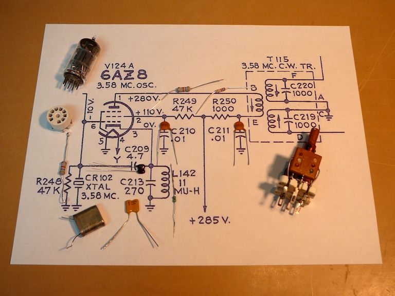 Here is the completed circuit lashed up to my CTC-4 chassis. Judging by the scope and my handy SW radio, the breadboard circuit does oscillate around the right frequency. The first photo shows the output at terminal F of the transformer: 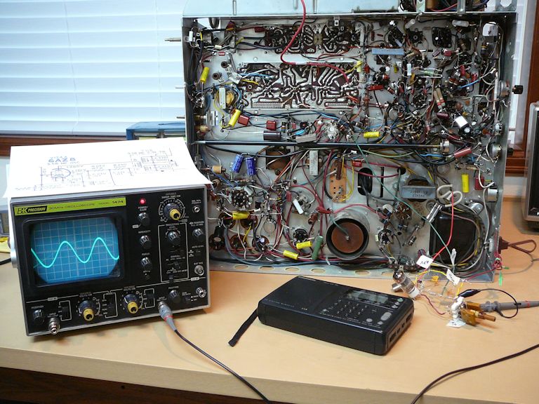 This photo shows the output at terminal A. Note that the new transformer's labeling is slightly different (terminals A and D are reversed).  Just as with the original transformer, one output is a simple sine wave and the other is a little more complex. Touching my DMM's probe to pin 6 of the oscillator tube in the breadboard circuit instantly kills the oscillation, so that little mystery is cleared up. I have to run out for some errands. Later on, I'll try to measure the amplitude of the signal coming out of this transformer. I can also adjust the slugs to see how they affect the output, and try whatever else seems sensible. Phil Nelson
|
 |
| Thread Tools | |
| Display Modes | |
|
|


 Hybrid Mode
