
|
|
|
#1
 01-15-2022, 02:41 PM
|
|||
|
|||
|
Zenith 23XC36 Tough Dog Trouble
A Zenith color decided to follow me home, hoping to avoid being upcycled. It's a remote model with power tuning. I managed to massage the set into fairly decent working order, temporarily, with the exception of the tuner motor which had a broken gear, and lack of fine tuning, which for some reason won't engage. (Will need to pull the tuner to try to address this)
Sam's https://drive.google.com/file/d/1Bpq...ew?usp=sharing 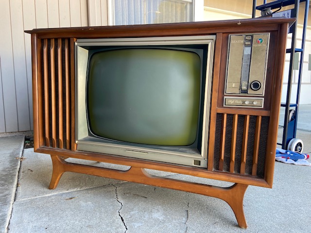 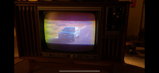 The color was always slow to come on, and after a couple days of running, I noticed the color not able anymore to achieve sync. I decided to try to finesse the chroma bandpass (A24), and while doing so, the pic started to drop out and I was left with very dark patchy video. Retrace lines were also visible. 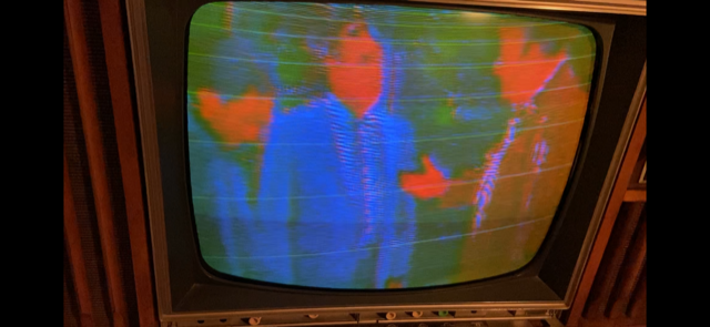 I tested all of the video, agc/sync and tuner tubes. Tested the Chroma, R-Y and R-B tubes.All were ok. Video amp transistor tested fine. Video detector and all other signal diodes tested fine. Source voltages and electrolytics test ok. Tested all resistors around all tubes concerned and all were within spec. Certainly no burnt or open resistors. After turning the set off and on, all that we have now is a blank raster. RF, IF and composite video does not get through. I've been banging my head trying to find the cause of this weird condition. I haven't dealt with a more complicated problem and I'm hoping a veteran can help point out something obvious I may have missed. 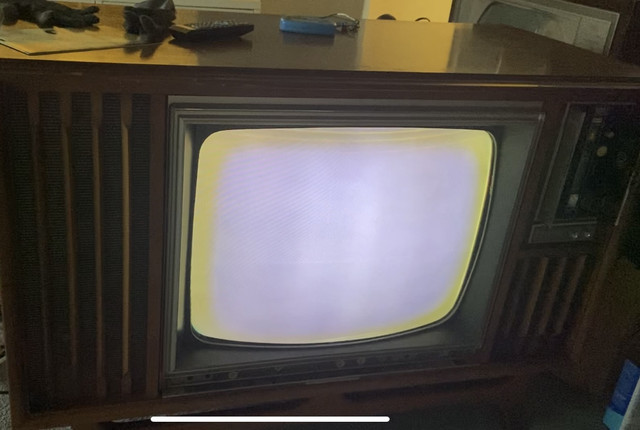 Injected signal from VA-48 into IF stages and there was no video, only sound. Injected composite into the Video output and only a very very slight pattern was seen. AGC Bias Biased point "A" on schematic, per alignment instructions, with up to +/- 25v and this had no effect on pic. Waveforms Injecting RF from pattern gen into the antenna terminals, no waveform was found in the IF stages. A sync pulse from the flyback was seen on the AGC plate, but no video sync pulse was found. Voltages V1 (1st IF) No appreciable voltages were found on any of the pins. V2 No voltages, except for pin 7, which has 241v on it V3 Normal voltages V4 (1st Chroma) No voltages found, except for an incorrect one found on pin 8 which was 199v (Should be 85) V5 (Vid. out) Normal voltages V6 (Sound/Sync) Normal voltages V8 (AGC) Normal voltages V10 (2nd Chroma) Pin 6 - 1.5v (should be 12.5), pin 7 - .26v (should be -25), pin 8 - 103v (should be 205), pin 9 - 207v (should be 240) Controls AGC pot was found to be in working order. Varying this control produced no change, other than slight brightness variation. Brightness and contrast controls did have an effect. Bias does vary brightness. Last edited by Jon1967us; 01-15-2022 at 04:15 PM. 
|
|
|


 Threaded Mode