
|
|
|
#1
 11-08-2021, 12:59 PM
|
|||
|
|||
|
Video can't get through IF on Portacolor
Recently acquired a mid 70's HE chassis PC. After the first step of replacing ceramic white tubulars in the H section in order to obtain HV, I set out to address the absence of audio. I was able to get video, but only on channel 4 (very weak signal on ch 3 and fine tuning doesn't seem to help.
Pic of set running before video went out (there was no audio at this point) 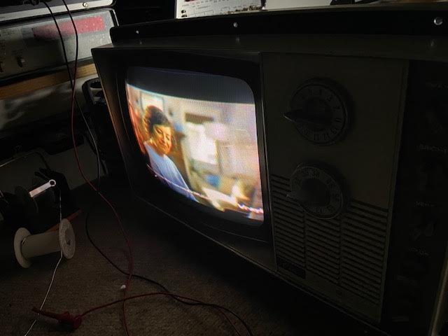 I had removed a couple of burnt resistors in the audio section and had to pull the board out somewhat to do this. after replacing the board HV became intermittent until I fixed a couple of broken/cold solder joints as a result of moving the board (apparently the solder joints had bumped a metal board screw housing) HV returned, but now video was completely gone. Injecting into the 2nd, 3rd and video amp produced a picture, but if I injected into the 1st IF, no pic nor sound. Why? well, probably because the voltage on pin 10 of V3 reads -17v (should be .1v). Something is dragging that pin down, but I couldn't see any source of negative voltage.  Further probing showed that on pin 9 of V6 (AGC) there was -70v! There should be .2v, according to the schematic. Keying waveform is correct here, and the correct amplitude. The 11BT11 tube tests fine. Examining the board, I see no cold joints or bad connections in the area of the AGC, but things are very cramped there as we know, so it's hard to be sure. I experimented by clamping the agc down (TP2) to where it should be, while I fed RF into the antenna terminals, and was able to get a weak picture and decent level audio. Just putting a Sencore bias box on that terminal clamped sufficiently, I didn't have to apply more than a volt. Something about that box that shunts voltage to ground, which is another issue. Shorting TP2 to ground, btw, has no effect on pic or sound. By the way, resistance on pin 9, V6 is well below what it should be - read 436k, should be 1.1M, according to Sams. Probably looking at a bad resistor, but what I don't get is the large NEGATIVE voltages on pin 9, V6 and pin 10, V3. The other voltages on pins 3 and 4, V6, are correct. Next step is removal of the chassis to have a closer look to lift a few resistor legs and to check again for cold/open joints. 
|
|
|


 Threaded Mode