
|
|
|
#1
 03-30-2017, 09:03 AM
|
||||
|
||||
|
Pilot tv
Was wondering, I have a pilot I recapped and works fine no problems however when I recapped it what I come up to was the b+ voltage was to low and after trying other 25z6 positive tubes it would not come up enough so I added a diode across the tube and the voltage was good. So if I wanted to eliminate that tube chances are I could leave that diode in place but then add a resistor to complete the string, I would have to figure out what value. But the other tube, the negative 35w4 my wonder is could that tube be eliminated , it would be the same as the other only what has to be done with the diode, just reverse it? I ask because I have read a few threads on the restoration of these pilots and what was said was that the 35w4 cannot be eliminated. I thought just turn the diode around, of course to make it the right polarity and add the resistor for the string. I don't know if I'm close but does 80 ohms 15-20 watts sound close for a 25 volt tube. And 100 ohms 15-20 watts for a 35 volt tube.


|
|
#2
03-30-2017, 10:43 AM
|
||||
|
||||
|
Timmy- Your wattages seem way high, so I pulled out the RCA tube manual. I have a 12" Pilot Tv125 so I'm interested in your application.
A 35W4 can always be eliminated but sometimes the filament is used as a voltage divider in some circuits, mostly for a 6-volt pilot light . See what is connected to pin 6 - the 6 volt heater tap. If 7-cathode is connected to 6, then you have a negative supply appearing at pin 5 that is the rectified, AC potential at pin 6. You will need two resistors to eliminate it in this case. The heater current is 150 mA, so resistor from 4 to 6 is 40 ohms @ 1 watt , 6 to 3 is 180-200 ohms @ 5 watts minimum. Your results may vary, Can you post a picture of the circuit? Often a 35W4 is employed to not only drop the AC a bit for a pilot lamp it can provide cheap fusing for the B+ supply because the 120 volts (to B- ground) at pin 4 is reduced at pin 6, and in most AC-DC radios, pin 5 is the plate where the AC connects to, 6 volts reduced from line voltage. To remove tubes, my motivation is to eliminate possible transformer-destroying failures especially in Zenith radios and HiFi amps like the 6X5 or 7Y4. But sometimes I sub diodes in where the elimination of a tube filament like a 5U4, etc saves about 10 watts on the primary transformer winding. My 1964 Zenith HiFi has 1N4007 rectifiers in for the 330 volt B+ instead of the 5Y3. I dropped the now 360 volt rectifier output voltage back to 330 with a 300 ohm on the rectifier cathodes before the first 47 uF filter cap. The 2x6BQ5 amp draws about 100 mA.
__________________
"When resistors increase in value, they're worthless" -Dave G
|
|
#4
03-30-2017, 11:22 AM
|
||||
|
||||
|
Consider that the voltage could be low for another reason, before modifying the design by adding diodes. Most likely either something is drawing too much current, or the voltage shown on the schematic represents an average value, which is subject to a tolerance.
How much too low is the B+ voltage? Can you show the portion of the schematic which is effected? I would say that you should check all resistors for tolerance and the tube bias voltages before changing anything. In the worst case you could put even more current through something which is already drawing too much current and cause damage, with the diode mod. If a circuit isn't working properly, it's better to find out why, instead of employing brute force type solutions to force the numbers to look good. Another thing to be wary of when changing out rectifier tubes for diodes, is that the tube has a warm up time, and the diode does not.. thus the B+ may surge to a value exceeding that of the filter capacitors voltage rating before the other tubes in the TV warm up. Last edited by maxhifi; 03-30-2017 at 11:26 AM.
|
|
#5
03-30-2017, 11:25 AM
|
||||
|
||||
|
I agree with maxhifi, but if you are interested here are the values for the resistors.
They probably said it couldn't be eliminated because it is in parallel with the 35B5 filaments. It can be replaced but you need to be careful to get a suitable resistor across that 35B5. Calculations are easy using ohms law. 35W4 = 35V @ 0.15A R = V / I = 233 ohms W = V * I = 5.25W I suggest using at least 10W for a safety margin. 25Z6 = 25V @ 0.3A R = V / I = 83 ohms W = V * I = 7.5W. Use a 15W or higher.
|
| Audiokarma |
|
#6
03-30-2017, 11:47 AM
|
||||
|
||||
|
Well the set works fine I was just thinking of this really because I don't know how the cabinet does not ignite because it gets extremely hot where those 2 tubes are. There are plenty of those tubes out there but if it were to much then I just as well leave it alone. When I got this pilot someone already literally redone the whole set and I mean every resistor, cap , even Micas were changed and all I did when I got it was put my own caps in and I could not get a full screen because of the low b+ now maybe the tubes I tried were not the best but I have read those posts on these sets and they also could not find out why they had low b+ IIRC 30 volts lower then the specified . So you are saying a 233 ohm 10 watt for the 35w4 and an 83 ohm 15 watt for the 25z6 . But then the diode would be in the neg position along side the resistor.
|
|
#7
03-30-2017, 11:59 AM
|
||||
|
||||
|
Quote:
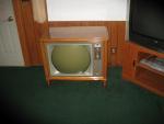
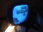
As for it getting hot.. well, that's kind of another sign that something is wrong, unless it's just designed to run hot. A rectifier which is supplying more current than its supposed to will have more loss, and generate more heat than usual. Do you have a photo of the TV? It's sure neat that a TV used common AA5 tubes, I'd love to see the set.
|
|
#8
03-30-2017, 12:35 PM
|
||||
|
||||
|
Well it's on the shelf and all hooked up since it works fine I just wanted to look into what it would take to do this. Maybe it's just me I feel as if the corner where the 2 tubes are gets hotter then the rest of the cabinet. After all these old sets were partial heaters in the day, lol. It's a pilot tv37.
|
|
#9
03-30-2017, 01:29 PM
|
||||
|
||||
|
Ah a true classic there, Timmy
__________________
"When resistors increase in value, they're worthless" -Dave G
|
|
#10
03-31-2017, 01:33 AM
|
||||
|
||||
|
I had the same problem (low B+ and very hot power supply) when one of the bias line chains was shorted to the chassis, so the bias voltage was low. The set was working pretty well with that.
__________________
To understand a bygone era, you should use things from it Last edited by Gleb; 03-31-2017 at 01:45 AM.
|
| Audiokarma |
 |
| Thread Tools | |
| Display Modes | |
|
|


 Linear Mode

