
|
|
|
#376
 03-16-2012, 07:06 AM
|
||||
|
||||
|
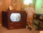
Here is an article from 1952 about RCA color. Nick, could this be the cabinet your chassis was in?
www.earlytelevision.org/color_tv_today.html 
|
|
#378
03-19-2012, 11:21 AM
|
||||
|
||||
|
Steve,
Proto set is on it's way to your door, I shipped it this morning. USPS w/insurance and tracking. I secured it inside the box as well as possible, hopefully they don't manhandle it. I put stickers all over it, so it's pretty obvious the contents are fragile. Nick
__________________
Evolution... 
|
|
#379
03-25-2012, 09:35 PM
|
||||
|
||||
|
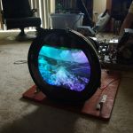
I made a CRT adapter mask to mate the proto CRT to a CT-100 cabinet, for the purpose of ETF demonstration. It's a board with trimmed 16" B&W mask secured to it, the board has mounting slots cut into it that are correct for the CT-100 cabinet so no modifications are needed. No hole drilling on the cabinet, just R&R the 15G with the proto stuff. I have also decided that having the bare CRT face in the cabinet could be a liability, so for safety's sake I will have a piece of plexiglass cut to the size of the opening in the cabinet to protect wayward fingers from getting zapped. This is what it looks like.
__________________
Evolution...
|
|
#381
03-26-2012, 06:43 AM
|
||||
|
||||
|
Nick, do you have extension cables to connect it to a CT-100 chassis?
|
|
#383
03-26-2012, 02:37 PM
|
||||
|
||||
|
I got the prototype chassis from Nick today and started documenting the remaining circuits. I'm starting with the power supply lines, then I'll do the sweep sections.
I have a new theory about the history of this set. The modifications are very unprofessional, with cold solder joints and midair connections. I can't believe that RCA engineers would do that kind of work. I think the set was abandoned by RCA after its life as a CPA prototype, and the later mods were done by someone who got the chassis, probably an attempt to make it work with NTSC.
|
|
#384
03-26-2012, 03:21 PM
|
|||
|
|||
|
Quote:
|
|
#385
03-26-2012, 08:20 PM
|
||||
|
||||
|
Steve, I agree that your assessment makes sense, although you would be surprised at some of the breadboarding techniques I have seen over the years. We had one fellow (X) who built prototypes by soldering a 3-dimensional haystack of parts onto a tin sheet. (His soldering was good, not cold joints.) Once it worked, he would unsolder all the ground connections from the tin sheet and put the haystack in the cupboard above his bench. These were known in the lab as "(X) piles."
|
| Audiokarma |
|
#388
03-27-2012, 07:17 AM
|
||||
|
||||
|
Quote:
So then you will be restoring this as a CPA set? If so is there any chance that at least the sweep and decoder sections could be working by the convention? I can get started on developing a CPA converter. BTW does anyone have the actual spec for CPA? Can we assume that most things just match NTSC (burst length, phase and position) and only the R-Y inverted every other frame? Darryl
|
|
#389
03-27-2012, 08:41 AM
|
||||
|
||||
|
I don't know how much I can get working by the convention. There are lots of cut wires and dangling components. If I can figure out where everything goes I may get most of the set working.
|
|
#390
03-27-2012, 09:49 AM
|
||||
|
||||
|
Quote:
Fink, Television Engineering, 1952 edition shows the "color-phase synchronizing pulse" in figure 417 on page 549, which may help. Pete Last edited by Pete Deksnis; 03-27-2012 at 09:54 AM.
|
| Audiokarma |
 |
|
|


 Linear Mode

