
|
|
|
#1
 12-28-2013, 02:50 AM
|
|||
|
|||
|
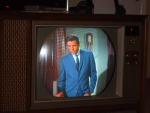
Restoring a 1963 Admiral ctc-12 clone
I decided to tackle this set , I can't believe how many tubes are messed up in it with shorts/gas and grid issues , amazingly one 6GH8 reads ok , I've replaced most of them with nos tubes ,there was a 2av2 in the 1v2 socket , would that work ? it was bad anyway so I put a 1v2 in.
the circuit breaker was replaced but instead of being installed wires run out to one mounted to the back , also theres an electrolytic can with wires running from the original wires , it just lays on the inside side of the set , these are things I will have to properly repair. when and if I get it up and running should I adjust the hv control for less voltage to anode so the fly doesn't get pushed as much as it could be ? what should the anode voltage be roughly ? I used to know but don't remember , I don't work on color sets enough. also the selenium on the convergence board should I be worried about it ? there are so many orange drops in it that I wont touch them unless theres some kind of issue in that section. anything I should be expecting or know about like the power diodes or other issues ? I don't see a degauser wire around the crt , just glanced at the schematic and don't see one mike 
|
|
#2
12-28-2013, 07:48 AM
|
||||
|
||||
|
I think the anode voltage should be in the 22KV range if everything is working correctly. Check your input thermistor (inrush limiter) if you have one. The leads like to come apart from the body of the thermistor. The resistance cold should be on the order of 10-15 ohms or so.
|
|
#3
12-28-2013, 08:33 AM
|
|||
|
|||
|
adj the HV will not do much to the flyback as it uses a shunt tube, and if working it just absorbs the excess current. there is an eff coil on the chroma board that should be adj for min current, this is all covered in the sams.
Leave the Se pack alone on the convergence, I have found that most of the time they are fine, you will know if the convergence does not work. the 2 vs 1 in the focus circuit, the 2 was used in the later CTC-16 the 12's had a resistor in the filament circuit of the focus. If you see a resistor on the focus tube socket then it prob needs the correct tube the 1V2. These sets often work just fine as found, I have several that have the orig filter caps. Sound like at least one may have already gone so I would at a min restuff that one. The film caps in the vertical circuit sometimes give trouble they are HV types 1600 IIRC. so if you have vert jumpiness or odd vert behavior then those should go. .0082 is the biggest offender as it takes the most punishment. Right off the plate of the vert out.
|
|
#4
12-28-2013, 04:12 PM
|
|||
|
|||
|
i will replace any film caps that are not orange drop or brown drops just to be safe , I just did the .001 at 2000 volts with a Sprague orange drop rated at the same value and voltage , the original is one of those that are in like a ceramic tube and didn't want to chance it but will test any that are removed for the fun of it just to see if they are leaking, I think there is another 2000 volt cap in the audio , I think I have a replacement for it too.
I never attempted power up due to the issues I already mentioned ( circuit break , electrolytic ) plus with all these tubes that are not good it really would have not been pretty , the 6dq5 was in bad shape so its hard to say if it would work with it anyway. I don't think there is a thermistor in the set but will check anyway
|
|
#5
12-28-2013, 06:03 PM
|
|||
|
|||
|
the ones in the vert may be bad even if orange (and prob if brown). the symptoms will be poor vert lin and maybe jumpiness.
The .001's are good to replace, I read somewhere the one on the primary side of the vert out is there to decouple any horz noise that is leaking back from the yoke windings. I think you are right about the thermistor, I don't recall seeing degaussing circuits until the 16's If you care to you can add a jumper wire off the cathode of the horz out tube. I routinely do this to make cathode current checks easy. I just snip the lead that goes the ground and add a length of insulated wire to that pin on the tube socket, then lead it out to the back of the chassis with a spade type connector that can be screwed down after checking current. I also will replace the caps that are often in the AC inter lock, may be bumblee bee in there across the line. There are 3 caps in the grid circuit of the 6GU7 diff amps. One of them that rest right between the tube and a power resistor is almost always weak when tested on a old school cap tester. If I have the chassis out I generally replace all 3 of those .01's. one last thing to check, there are a couple jumper wires on the chroma board often are rotten and will break right off. If this happens the screeen will be tinted one solid color like the screen drive is turned wide open. I have seen a lot of these break so its a common problem. You will know for sure if one of the big power resistors is cold on chroma board (one of the wires feeds thru that). They can look OK but still be broken. A slight tug upwards will reveal that.
|
| Audiokarma |
|
#6
12-28-2013, 10:02 PM
|
|||
|
|||
|
Ok you guys would know this has a 21FBP22 in it not the 21FJP22 as listed in the schematic / sams , is this an older crt ? any advantage or disadvantages ? it looks like admiral date code 63-11
ok I will replace the caps in the vertical section as suggested , the set doesn't use 6GU7 tubes ,uses 6GH8 chroma bypass amp/color killer , 6JU8 chroma sync phase det killer det , 6GY6 z demodulator , 6GY6 X demodulator , 12BY7 Video out , 6EW6 burst amp , 6GH8 chroma reference osc , 6FQ7 b y amp r y amp , 6FQ7 horz blanking amp g y amp , that's the color board. the jumped electrolytic that I mentioned had a hand written installation of 1979. heres a question can I replace that electrolytic 160uf @ 250 volts with a 250uf @ 350 volts or a 470uf @ 250 volts or is going too high going to mess things up ? he did something interesting , its a multi section can and all the values were connected together to make 140 uf which is 20 uf too low but it must have worked or was close. what pin on the horz out are you referring to and if it is too high I have to change some resistor / resistors ? oh yeah the .0082 @ 1000 volts could I put a .01 there ? mike Last edited by kramden66; 12-29-2013 at 02:35 AM.
|
|
#7
12-28-2013, 10:19 PM
|
||||
|
||||
|
The CRT's are the same. One has a bonded safety glass and the other one does not. Some have a clear safety glass and others are frosted and tinted. You could use a 250uf cap but would be better to use something closer. The voltage rating of 350 is good.You can always go higher but never go lower.What the tech did was OK.The tolerances of those can caps are usually 20% either way
__________________
"It's a mad mad mad mad world" !! http://www.youtube.com/user/mwstaton64?feature=mhee
|
|
#8
12-29-2013, 02:31 AM
|
|||
|
|||
|
surprise surprise surprise as gomer pyle would say , I tested the 3 capacitors I removed , the .001 @ 2000 volts is ok , the .047 @ 600 volts is ok and the .01 @ 400 volts is ok , so looks like replacing others would be a waste but I will check the ones that are known to go or be bad , looks like I'm just going to do the electrolytic capacitors since one was bad in 1979 I wont chance the others and slowly power it up , I will check power resistors and anything that might not look right before doing so.
so this set has a non bonded safety glass (21FBP4) ? , if that's the case it sure is tempting to clean it but a lot of work , theres is a couple spots that look odd , I thought maybe it was cataracts but this may be just dirt , hopefully it's not annoying while watching . sorry I don't have pictures and step by step on this restoration. mike
|
|
#9
12-29-2013, 09:34 AM
|
|||
|
|||
|
I would stick with the 0082 if that is what is there, and go high on the voltage, so if its a 1600, I put in 2000, the price is about the same and the fit will be better anyway as old caps are larger than new ones.
sorry about the 6Gu7, I should have checked, the caps that have been bad on those is the .01, its right behind the 6FQ7 that is close to the middle of the board (not the one on the end), but I replace them all anyway. I can say that its hard to tell if there was any change (the bad test was the fuzzy eye opening on the value check, leakage tested fine). I presume you are checking the caps with a old school cap tester that can apply working voltages, those little hand held DMMs are worthless when checking caps since the failure mode generally does not show up at the low voltages they use. I replaced the .001 simply because my cap tester maxed out at 450v so I could not check them at the rated voltage. Most of the time the film caps are ok, The ones that have given me trouble in the past have been those few in the vert circuit. I generally dont do mass recaps on sets of this era without at least trying to see if it works (that way you have a base line to compare to). The issue on mass recaps is the introduction of user error, if you are good at diagnosis then you can generally find the problem but if not you can make a real tough dog out of what may have been a working set. RCA with its PCB make wiring errors hard to do, but there is still the possiblity of value errors, .001 for a .01 as an example. What I do is when replacing (that I think may be a problem) is remove the cap, test with the cap tester, if bad I will leave the cap tester alone and check the new cap going in (always a good idea, I have had bad brand new caps). By leaving the cap tester settings unchanged I compare the value that came out to the value that goes in (even bad caps will give an indication of value on the old school cap tester). If I do not have to adj the settings much then that is a double check that the value is correct (besides just reading the cap values). So you not only check the part going in (value and leakage) but also confirm the value is correct. This is esp helpful with the new numbering like 103 for .01 etc... Last edited by DaveWM; 12-29-2013 at 09:47 AM.
|
|
#10
12-29-2013, 12:18 PM
|
|||
|
|||
|
yes old tester and applied voltage to caps , I will do the vertical caps to be safe , one of the annoying things is to pull something apart , put it all back together to find you have to open it up all over again.
one board (either the color or horz vert ) clearly says rca on the underside , also the sams where it points out parts locations in photos shows a color board that has bigger tubes then whats inn the set and schematic and tube location in the sams.
|
| Audiokarma |
|
#11
12-29-2013, 01:11 PM
|
||||
|
||||
|
On the non bonded CRT's, they have a rubber gasket around the edge of the safety glass that oozes an oily substance that gets on the CRT face and inside of the safety glass. Unfortunately, the only way to clean it is by removing the CRT. I did it with my '67 Admiral roundie because it bothered me but it may not bother you. I would just leave it to very last after you get it running.
__________________
"It's a mad mad mad mad world" !! http://www.youtube.com/user/mwstaton64?feature=mhee
|
|
#13
12-29-2013, 08:12 PM
|
||||
|
||||
|
On higher hours RCA clones I'd check all the caps on the color board. I have seen some sets where a good portion of the orange drops there were bad, and the .01 orange drop nearest a tube actually was split open!....It was not shorted, but it did not have a defined value when tested.
__________________
Tom C. Zenith: The quality stays in EVEN after the name falls off! What I want. --> http://www.videokarma.org/showpost.p...62&postcount=4
|
|
#14
12-30-2013, 01:21 AM
|
|||
|
|||
|
I will check other caps to be sure , the previous owner did install a fan that looks like it might be from a record player so it was kept cooler while running then sets that didn't have a fan , I guess it would explain why there was so much dust under the chassis , normally I find it cleaner there , this fan pushed air around in there so it helped keep the air circulating , the cover to the hv / fly is not present , I'd guess to help keep things cooler, I don't see any signs of things being over heated, I remember years ago when fixing sets for neighbors seeing caps that were orange drop near a tube and they had that burned look on the side .
I guess I'm going to have to use the 470uf in place of the 160uf or keep the replacement in and check if it gets warm or hot , I don't have anymore caps to replace with unless I waste a 100uf @ 450 volts hooked to two 33uf caps or a 47uf , the circuit only requires a 250 volt cap so I'd be wasting the 450 volt cap .
|
|
#15
12-30-2013, 01:23 PM
|
||||
|
||||
|
If that 160uF cap is part of a voltage doubler circuit (which was common around then) I would recommend keeping it the same value as the other doubler cap...I'm fairly sure there is a reason why all doubler circuits I've seen use the same value for both caps.
__________________
Tom C. Zenith: The quality stays in EVEN after the name falls off! What I want. --> http://www.videokarma.org/showpost.p...62&postcount=4
|
| Audiokarma |
 |
|
|


 Linear Mode

