
|
|
 |
|
|
Thread Tools | Display Modes |
|
#1
 10-30-2011, 11:58 AM
|
||||
|
||||
|
Setchell Carlson...588 dial, 407 cab, 420 chassis(?) Serious need of a schematic.
Hi guys...sure could us some help.
First time poster here at videokarma, but spend a good deal of time at AK. This one is a puzzler. After researching the unit, it appears to be a "blended" radio. I picked up this Setchell Carlson tube radio about a month ago at a Garage sale for $15.00. It was a "sort of working" unit. The broadcast sound was very "mechanical" like an a emergency weather broadcast. Could be the hybrid speaker. By all the photos I've seen the cab is a Model 407, except the for the dial face (attached to chassis) and trim, which looks to be a 588. It appears to be the original dial face trim. But the 407 and 588 schematics do not show the same tube line up as mine. I can't seem find a Setchell Carlson schematic that sports my tube configuration anywhere. A 330 is close. So after much searching with no luck finding a schematic, I decided to just swap components value for value. This unit has been worked on before as there were plenty of component clippings still left at terminals. My efforts yielded only static. So without a schematic, any further effort would be a shot in the dark at best. All tubes test low end of good. The bottom 25L6 has been replaced with a 25Z6. And...I'm guessing the UTAH speaker is a replacement...or were they common to setchell carlson? Looks like a field coil / PM hybrid Any help and info on this radio would be appreciated. Martin P.s. I am being mindful of the "hot chassis". 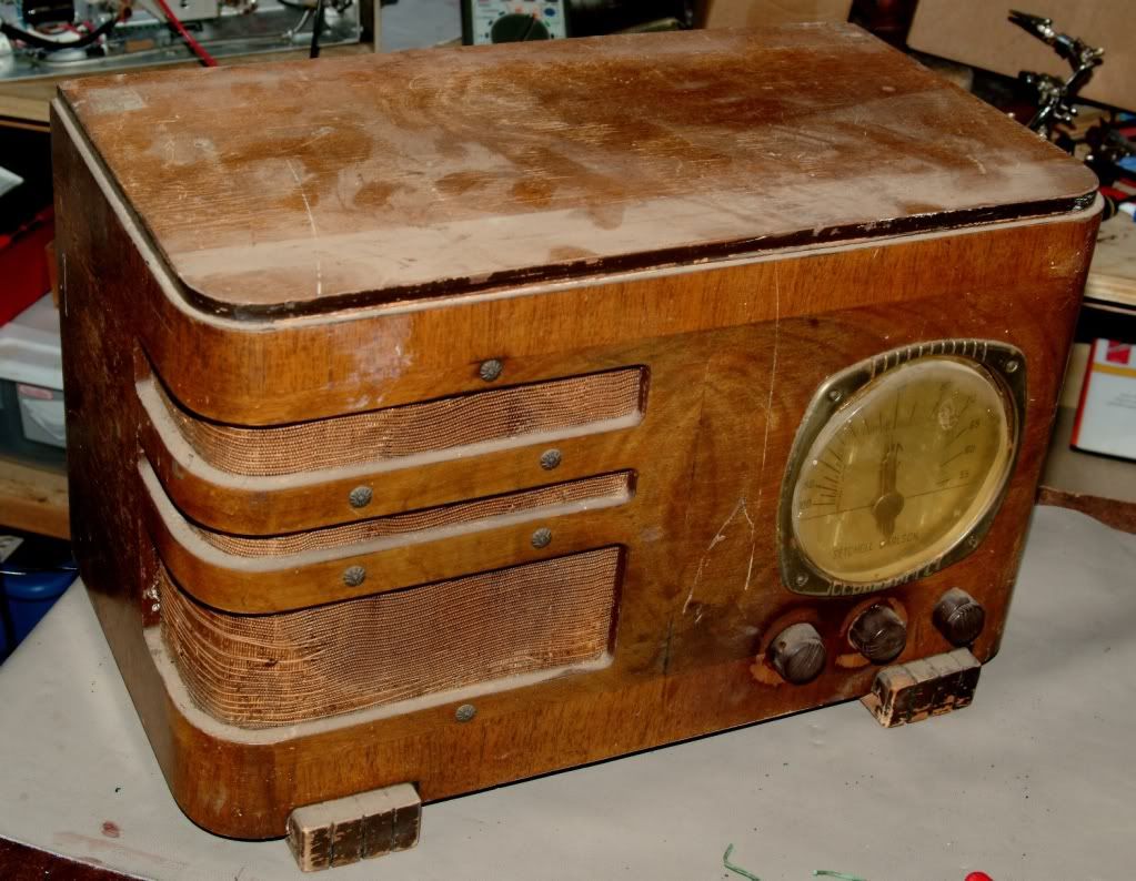 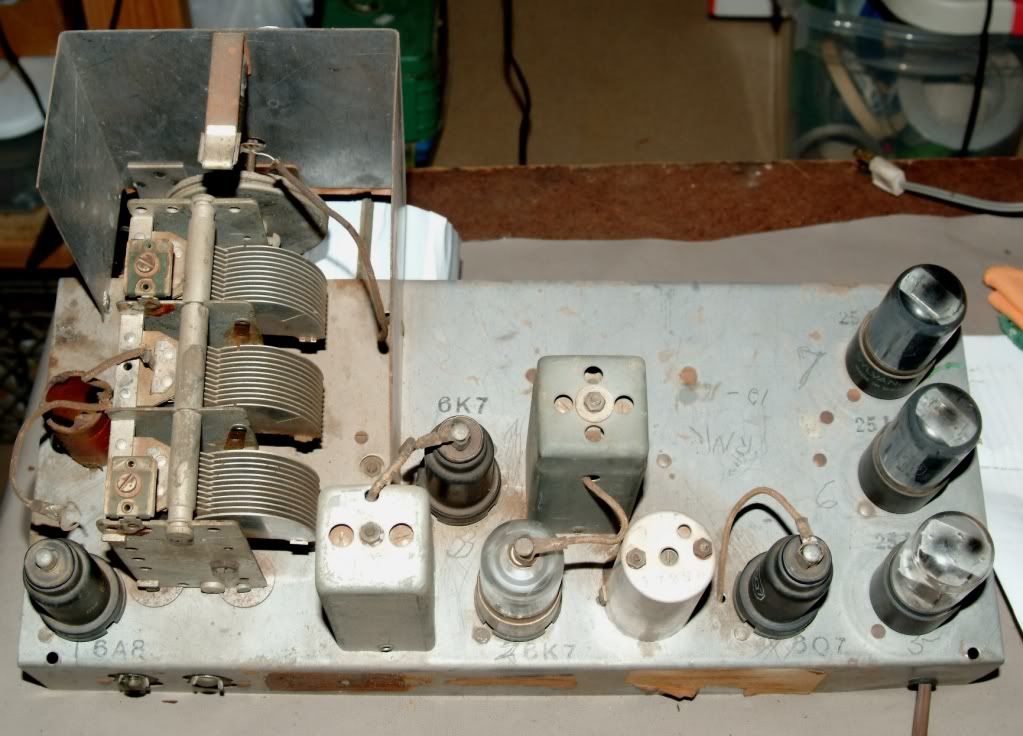 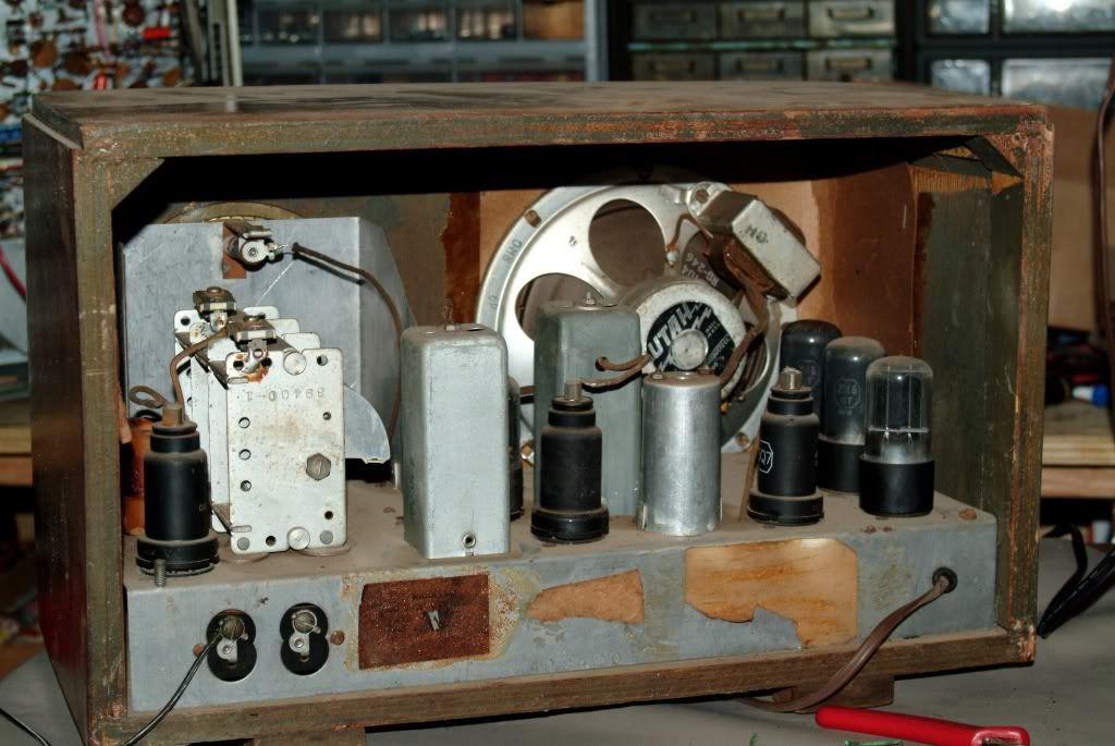  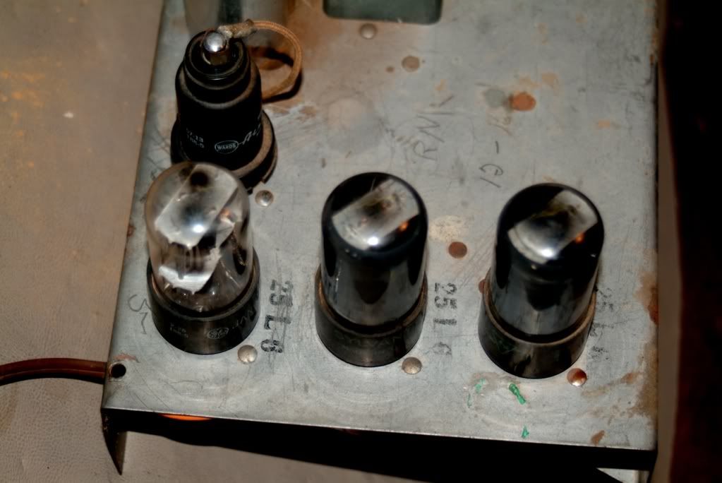 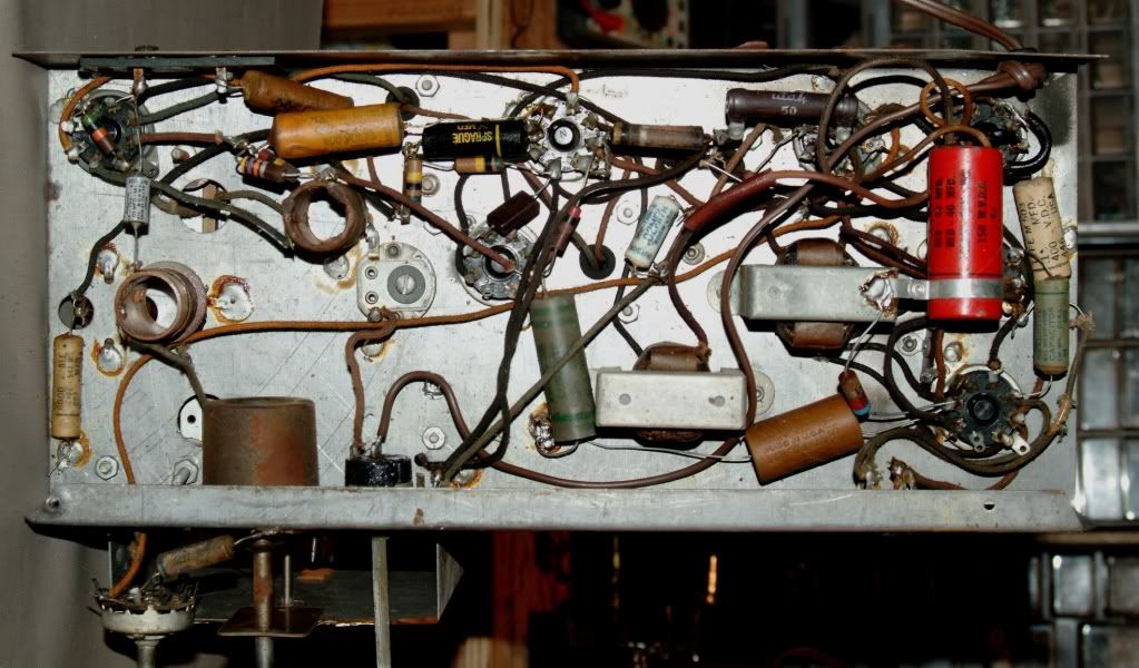

|
|
#2
10-30-2011, 05:11 PM
|
|||
|
|||
|
First you need to put the grid cap back on the 6A8.
Measure the supply voltages on each plate and screen grid. You should get at least 50 Volts or up to about 100 Volts. See that the cathodes all draw current. Then see if the local oscillator is running. You really need an isolation transformer and an oscilloscope to do this properly.
|
|
#3
10-30-2011, 09:16 PM
|
||||
|
||||
|
bob91343,
Thanks for the help. The photo is only a reference photo of the units original state. Believe me, the cap is on. What I really need is an ID on the chassis and schematic to match. But again, thanks for the reply. martin
|
|
#4
10-31-2011, 09:33 AM
|
|||
|
|||
|
Setchell- Carlson made a lot of 32 volt farm sets. It looks that it was converted to 115 volt ac-dc. First thing I would do is the capacitor heater dropping trick after a complete recap. Not too many of that make around. Good find.
PS. The voice coil in the speaker is probably dragging on the pole piece. It gives that real mechanical sound.
|
|
#5
10-31-2011, 01:46 PM
|
||||
|
||||
|
dieseljeep,
Being a new hobbyist to tube radios and not having much of a electronics background, a lot goes right over my head. I have recapped the unit to the best of my abilities with the limited information that is present. Basically I recapped it and replaced the resistors value for value. I am not familiar with the "capacitor heater dropping trick". Can you expound? Since you mention that it has been converted to 115V from 32V, I'm guessing that a schematic would be usless anyway...correct? Hmmmm? Can I bypass the fieldcoil xfmr and test the speaker on a common speaker lead? I'll keep plugging away at it. Thanks Martin
|
| Audiokarma |
|
#6
10-31-2011, 07:11 PM
|
|||
|
|||
|
If it's not working, a tube isn't drawing the right amount of current or a tuned circuit isn't tuning. If you have limited experience with this stuff you ought to find a mentor to walk you through. What test equipment do you have?
A schematic diagram wouldn't help much; all those circuits are pretty much the same. A superheterodyne with IF of most likely 455 kc (more rarely 262.5 kc). If the local oscillator is running, you have a good start. If not, you need to get it running. That's the 6A8 circuitry. Do you get a hum when you put your finger on the 6Q7 cap? If so, the audio works okay. All that's left are the IF stages, the 6K7s.
|
|
#7
11-01-2011, 01:07 AM
|
||||
|
||||
|
Gentlemen,
Before I go any further with questions, I'm going to go over what I've already done and double check everything. So far I have found a capacitor that I replaced with the wrong value and a broken solder to ground. Also I need to digest what you have asked of me so far. The revelation that the original schematic wouldn't help much has given me a bit to think about. I took a good number of "before" photos, and I'll post those with like "after" photos. Maybe the problem is obvious to "experienced" eyes. Bob91343, The unit was working before I did the component swap, albeit, not very well. At present all I get out of it is hum. The hum is volume sensitive and increases in pitch as I move the tuner up in kilocycles. I also have what sounds to be a brief arching in the on/off switch about 5 sec. after it's switched on. I don't get any difference in hum when I touch the cap on 6Q7. The only test equipment I have is an emissions tube tester. Dieseljeep, Thanks for the nod on the find. It gives me some sorely needed encouragement. The cabinet is in wonderful shape. I've got it stripped and the inlay is really quite nice. I'll need to replace the grill cloth and a new dial cover...crystal or plastic. I haven't decided. I really do enjoy restoring things and don't give up easily. My time with tubes has been short. My only other venture was a restoration of a Fisher 800c. If you feel inclined to have a look you can view it here. It is from start to finish, so it's quite long. But it will give you an idea about what my level of comprehension is. http://www.audiokarma.org/forums/sho...d.php?t=373498 Thank for taking the time to help. I'll post again when I've got something worth going over. martin Last edited by marloubow; 11-01-2011 at 01:14 AM.
|
|
#8
11-01-2011, 08:37 AM
|
||||
|
||||
|
Don't think you need to do the capacitor drop for the heater voltage, seems to be already taken care of. In the underchassis shot, underneath the 6Q7, I see what looks like a 50 ohm wirewound resistor. I did the calculations and that would be about right for dropping the heater voltage if you used 115V as the line voltage. For 120V line voltage you'd need 70 ohms. Although the calcs say smaller, I'd use a 20 watt for either ohms value for it to run cooler. Don't know what watts the present one is. The 50 ohm is probably OK but I'd measure voltage at the tube heater terminals to see how close it is to spec. I think I'd also move that resistor away from directly underneath the tube socket, towards the rear of the chassis, moving any wires in the way. That resistor will get hot.
The first thing you need to do to get the set working is for the audio section to work. If it's not working you'll never know if the IF and RF are since you can't hear them. Always start at the speaker and work backwards. We know the speaker works since you can hear hum. You can use the diagram you found around the 6Q7 and the two 25L6's and check your wiring. With a two foot piece of insulated wire, bare the end of it and touch to the grids of the 25L6's, one after the other. Should hear hum. With the volume halfway up, should hear loud hum when touched to the center terminal of the volume control. Check the grid wire going to the top cap of the 6Q7 and see if it has continuity or shorting anywhere. Check all components in the audio section for wiring mistakes or bad components.
__________________
Reece Perfection is hard to reach with a screwdriver.
|
|
#9
11-01-2011, 09:37 AM
|
|||
|
|||
|
Martin. There's very poor coverage of Servicing information in Riders for Setchell-Carlson. My 6volt tombstone farm radio isn't in there either. It's a real neat design using engineering I haven't seen before.
Your radio looks like it used three 25L6's instead of four.
|
|
#10
11-01-2011, 12:18 PM
|
|||
|
|||
|
No difference in hum while touching 6Q7 cap indicates a problem in the audio section. If there is a change when tuning, it seems the IF may be oscillating.
Check deeper for errors. This is why I never advocate a total recap - too many chances for error. Once it works, you can change a part at a time to make sure you aren't screwing up. Check that the B+ is adequate. You'll need a voltmeter for that. See if the ripple is excessive; you will need a 'scope for that unless you have a spare electrolytic capacitor to parallel the existing one. If the hum goes away, you need to fix the power supply. One sneaky way to check the B+ is to run the radio, pull the power plug, then quickly short the B+ to ground with a screwdriver. Should get a major spark.
|
| Audiokarma |
|
#11
11-02-2011, 11:53 PM
|
||||
|
||||
|
Gentlemen,
I'm hoping this will help you help me. I haven't got thru all that has been suggested, but I'm working on it. bob...which component is the "local oscillator"? Reese...it is a 50ohm wire wound cap and it does get hot. Watts not specified. Lesson learned on recapping all at once. Voltage at the bulb (not working, filament intact) (-)1.0mV On the 6Q7 datasheet it looks as though the screen goes to ground and didn't know what to make of that. The rear 25L6 looks way out of whack. Yes? I've checked continuity on all open ended wire and found no breaks. I've been looking around the net reading about older radios and found this in an article on the All American Five. I'm sure you guys know this stuff, but I found it interesting and informative...for a noob like me. http://en.wikipedia.org/wiki/All_American_Five Thanks again for the help. Martin 
|
|
#12
11-03-2011, 11:06 AM
|
|||
|
|||
|
That rear tube marked 25L6 is really a 25Z6. It's used as a rectifier in the conversion. It has two plates and two cathodes that should be paralleled. The original tech should have re-labelled the chassis. In the radio's original state, they had the plates and screens on all the tubes running at 32 volts and the audio output was very weak. That's why they used three 25L6's.
|
|
#13
11-03-2011, 01:53 PM
|
||||
|
||||
|
I'm going to suggest a way to tackle this beast. I can see how some of the wiring goes, but some parts aren't clear from the pix. Can we do it section by section? Some of this will be going over sections that are already working, but may not be quite right. I'll number the items for reference. Please confirm or explain each.
PLEASE anyone chime in here with any suggestions or if I flubbed anything. All tests with set unplugged. 1. The tech who wired this for 120VAC made it into a hot chassis set. Notice that one side of the line goes to the power switch and the other side of the switch is grounded to chassis. It is dangerous like this in that if the hot side of the line goes to the switch, the chassis with the switch on will be a shock hazard with respect to ground. Even with the switch off it will be a shock hazard if the hot side of the line goes to the rectifier as the chassis would be hot back through the heater string. You can find the other errors and get the radio to work this way, but you should use an isolation transformer between the set and line. Also you should be insulated from a concrete floor and be careful and don't rest your arm or other hand on the chassis when taking readings. The live chassis can be made safer with a floating B- bus but I'd say get the set working first and tackle that as a later project. 2. 25Z6: pins 3 and 5 are tied together and one side of the line cord goes to them. 3. 25Z6: pins 4 and 8 are tied together and go to the + side of the first electrolytic cap. The - side of this cap goes to chassis ground. Be sure you have + and - correct on all electrolytics. It looks like you have two electrolytics with their + sides tied together. Why is that, and where are they in the circuit? There's another underneath them. What are the mfd values and voltage of each? 4. 25Z6: cannot see but there should be an approximately 1000 ohm 1 watt resistor also connected to the + side of the first electrolytic cap and the other end of the resistor should go to the + side of the second electrolytic cap. The - side of this second cap goes to chassis ground. Where does the + side of this second cap go? 5. 25L6's: tube at front of chassis near speaker plug let's call tube A, other one tube B. Tube A has a wire from nearby input transformer going to pin 5 (grid 1.) Should be another transformer wire to pin 5 on tube B? What is resistance between the two pin 5's? Is there a third wire from the transformer on the same side as the other two and if so, where does it go? What is resistance between this wire and each of the two other ones going to the two pin 5's? Transformer can't be open or shorted or there'll be no audio. 6. 25L6's: each tube should have separate wire from pin 3 (plate) to speaker plug. Another single wire from speaker plug to both pins 4 (screen) jumped together. Pin 4 on tube B appears to have another wire which should be going to B+ (the + side of the second electrolytic.) Does it? 7. Unplug the speaker. Determine which wire going to the output transformer on the speaker is the one that goes to pin 4 on tubes A and B. Connect one lead of your ohmmeter to this wire at the plug. Check the ohms between this wire and each of the other two wires going to the transformer in turn. They should be about the same. 8. 25L6's: there is a resistor (what ohms?) from pin 8 (cathode) to ground on tube A, and an electrolytic cap (what mfd. and volts?) from same pin 8 to ground. Is there a similar arrangement on pin 8 of tube B? That's enough for a while! 
__________________
Reece Perfection is hard to reach with a screwdriver. Last edited by Reece; 11-03-2011 at 05:19 PM.
|
|
#15
11-03-2011, 05:09 PM
|
||||
|
||||
|
There are some more components around the 25L6's but the above should cover the most important ones (I hope!) Get the above straightened out before proceeding.
9. 6Q7: pin 3 (the triode plate) goes to the interstage or input transformer that feeds the two output tubes. The other wire coming from that side of the transformer should get B+ to feed the 6Q7 from somewhere, probably from the + side of the second electrolytic filter cap? Check ohms between these two transformer wires: transformer should not be open or shorted. 10. 6Q7: pin 8 (cathode) either goes directly to ground or to ground through another component or two? 11. 6Q7: top cap (grid) should go through a cap to the center terminal of the volume control. Can't tell from the pix but this line should not be grounded anywhere or any signal will be shunted to ground and there will be no audio. Test: remove the clip from the grid cap of 6Q7, turn set on and volume up, touch grid cap. If loud buzz, audio section is working and something seems to be shorting out signal back to the volume control.
__________________
Reece Perfection is hard to reach with a screwdriver. Last edited by Reece; 11-03-2011 at 05:20 PM.
|
| Audiokarma |
|
|
|


 Linear Mode

