
|
|
|
#31
 08-02-2014, 01:48 PM
|
||||
|
||||
|
The new resistor fixed the focus problem. I tried magentizing a
screw for a replacement purity magnet. It was not quite strong enough. So I ground the top of the screw flat and superglued on a small piece of a refrigerator magnet. This made it work OK. Getting passable convergence was fairly easy. I got around to playing with the B+adjustment resistors I had installed. The B+ was at 355 and I got it up to 385, which Sams says i Correct, so I left it there. The only remaining problems are probably designed in ... bright colors in large areas ruin the luma. Actually my Pilot TV-37 ha the exact same problem until I realigned it to not overemphasize 3.58 MHz. The other problem is serious blooming on white screens. Pictures this evening when window reflections wont be a problem. I'm not showing Dorothy ... my copy is pillerboxed. 
|
|
#32
08-03-2014, 08:21 PM
|
||||
|
||||
|
Didn't take pictures last night. I decided that it still
was not right. Guess was that the drop in luma when full brightness full saturation R appeared was caused by clipping in the detector because the luma carrier was too far down on the 45 to 46.5 MHz slope, and the chroma was much much too high. I had looked at the response crudely using a CH 10 rf sweep and it looked like a sin curve from 46 to 41.25 MHz for the IF. I was unsure of this since I didn't have a proper bias box. Today I did an alignment. But there was a problem: the cheapo Eico generator I got off Ebay leaked RF out the line cord. That was fixed by removing the knot from the line cord, shortening the leads to it, and installing new and better safety caps as close as possible to the line in, the ground end soldered directly to the chassis. The caps should be broadly series resonant somewhere between 40 and 160 MHz. This worked. Then I did the "Overall IF Alignment" on page 19 of the RCA service manual. All the traps were already quite accurate so I touched only 1T109, 1T110 and 1T111. This took a while with careful notes of where I left everything since I wanted to be able to go back if needed. 1T109 and 1T111 were within 160 degrees of correct, but 1T110 had to go 1 1/3 turn clockwise. This resulted in an almost perfect curve. The little bump below 41.25 MHZ was a bit smaller than shown in Fig. 27. I had earlier today generated true proper test patterns for an IQ color set. I will make these available somewhere. They are jpeg files generated in Photoshop by calculating Y, I, and Q levels mathematically for various color patches. The 2 main files have +I, -I, +Q, and -Q all at the same color level and the luma calculated to make high saturation without going more than 5% blacker than black or whiter than white. One file has full bandwidth color (to 4MHz) in the jpeg, the other has I limited to 1.5 MHz and Q to 0.5 MHz. (This was done by converting to Yab in Photoshop and applying a "motion blur" to a and b only.) The -I to +Q transition was filtered at 0.8 MHz. I then copied the files to my Sony Blueray player and played them. The result on the filtered IQ test are amazing. There are no off-color fringes except a tiny one in -Q. The +-I transition is clearly three times the resolution of the +-Q one. The unfiltered file shows the expected 0.5 to 1.5 MHz crosstalk that so mars cheapie color decoders (and encoders). Its not as good as my 55 inch LCD TV on the same NTSC, but its close. And the problem with saturated reds and yellows is gone. Next is dinner.
|
|
#33
08-03-2014, 11:44 PM
|
||||
|
||||
|
Here are final result images. These are taken with a digital
camera and processed in Photoshop. I have not changed the color but did brighten some. All were processed in Photoshop taking care that no pixel was overloaded. The non-CRT dot images were blurred correctly before resizing to avoid moire. These are off-the air digital TV images. The next post contains technical images.
|
|
#34
08-04-2014, 12:01 AM
|
||||
|
||||
|
The first one is the IF response. The marker is at the video carrier.
The rest are of the picture I made and played on my Blueray player that contains images of R G B fully saturated but different brightness on the top row, and +I -I +Q -Q on the bottom row. The transitions on the top row were not filtered in Photoshop (before playing the test file ... not the camera images), while the bottom row was filtered to the NTSC specs for the +_ I and Q transitions, and filtered at about 0.8 MHZ for the -I to +Q one. The final image is the histograms made from my digital camera images of the flat (appropriately blurred) parts of the patches. Its not perfect, and I also note that I don't know what the gamma of the camera is ... this is not photometric.
|
|
#35
08-04-2014, 03:59 PM
|
||||
|
||||
|
One more piece of data. I took the picture in the last post of the
+I > -I and +Q > -Q transitions, smoothed out the dots, and converted from RGB to Lab. Lab is similar but not identical to YIQ. I rotated the UV axes to actually be as close as possible to IQ. I then made grayscale plots of "LIQ" for (top three) the I transition, and three for the Q one. These are in fact highly contrast enhanced. These do show some cross-interference between I and Q and also show the fact that I has wider bandwidth, though the latter is better seen in the thumbnail of the color pictures.
|
| Audiokarma |
|
#36
08-04-2014, 10:15 PM
|
||||
|
||||
|
Wow - great detailed work.
I have a question about your +/-I and especially +/-Q signals: When you filtered the Q, did you delay the Y to match? and did you also delay the I (less) to match Q? The magenta/green Q transition appears to be later than the Y transition (the colorless area is on the right side of the brightness step). If you turn down the color to get monochrome, where does the Y transition appear compared to the Q transition?
|
|
#37
08-05-2014, 12:58 AM
|
||||
|
||||
|
Some amazing work there! I am quite impressed.
__________________
Chris Quote from another forum: "(Antique TV collecting) always seemed to me to be a fringe hobby that only weirdos did."
|
|
#38
08-05-2014, 07:42 AM
|
||||
|
||||
|
Quote:
Photoshop left the center of the transition at the same "time" for each channel. I don't know if it is supposed to be done in the camera chain. What I did would be correct IF the camera chain does the correction AND the Blonder-Tongue modulator does not. In any case, You can tell for yourself whats going on by looking at the B&W images I posted of the individual channels. Its visible in the original JPEG before being played. Attached. Note that the Y really IS unfiltered in this file ... you can see that in Photoshop by converting to Lab.
|
|
#39
08-05-2014, 09:26 PM
|
||||
|
||||
|
Ah - I think I see the problem. You did the filtering for the source signal as some sort of Photoshop motion blur, correct? It is showing very sharp transitions into and out of the "blurred" area between the magenta and green. This is not normal filtering, and results in strange effects.
Here are some simulation results with proper filters in Photoshop. The simulation includes the modulation and demodulation, so cross-color (orange/cyan moire' in striped awning) and cross-luma (dots on vertical edges of the bars) are visible. The smaller +/-I and +/-Q bars at upper left center have no Y variation, so you are seeing just the effects of I and Q there. There is some anamorphic stretch due to adjustment to get the color subcarrier dots approximately correct coarseness. Original:  veg market with IQ bars and cbars by old_tv_nut, on Flickr veg market with IQ bars and cbars by old_tv_nut, on Flickrchroma on gray with transmitter I and Q filters: 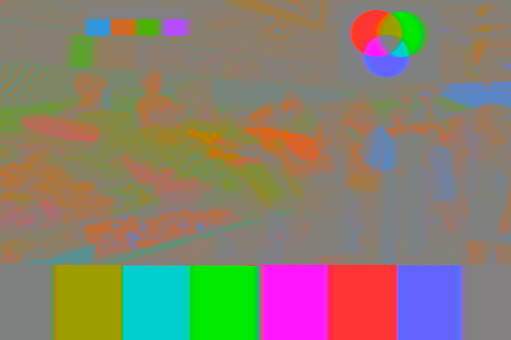 chroma in IQ filtered by old_tv_nut, on Flickr chroma in IQ filtered by old_tv_nut, on FlickrDemodulated chroma on gray with both transmitter and receiver I and Q filtering: 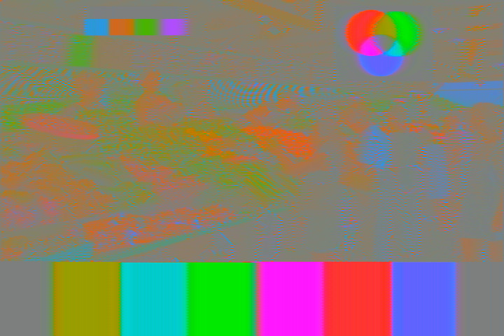 chroma out IQ code + IQ decode by old_tv_nut, on Flickr chroma out IQ code + IQ decode by old_tv_nut, on FlickrDemodulated I: 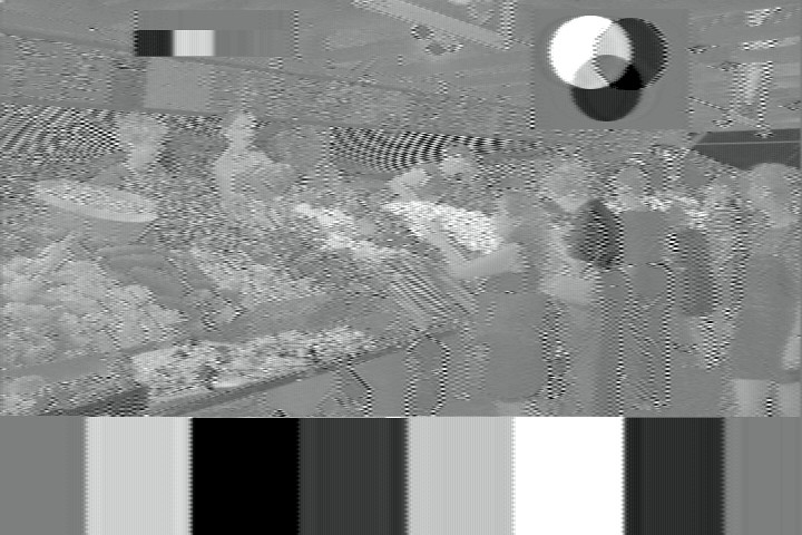 I out as mono by old_tv_nut, on Flickr I out as mono by old_tv_nut, on FlickrDemodulated Q: 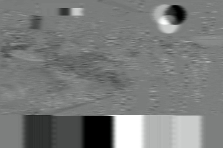 Q out as mono by old_tv_nut, on Flickr Q out as mono by old_tv_nut, on FlickrFinal output: 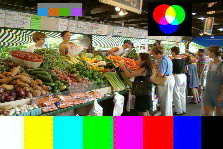 final out IQ code + IQ decode by old_tv_nut, on Flickr final out IQ code + IQ decode by old_tv_nut, on FlickrBoth the cross color and cross luma are more visible than normal because they are stationary.
|
|
#40
08-07-2014, 10:41 AM
|
||||
|
||||
|
Last night I tried to receive our actual OTA real NTSC Ch. 39 and
failed. I also failed to find a radiated local oscillator signal at UHF with a spectrum analyzer, though I see it at VHF. I should add that the signal is weak, but works OK on other sets because there is a 16 dB gain 0.5 dB NF preamp. Could this be a weak oscillator tube? It tests excellent. Are all of these CT-100s actually supposed to get UHF, or only some of them? Could bad blooming be due to use of a 1X2A rather than 1X2B? I forget what I found in our old stock ... it tests good offscale.
|
| Audiokarma |
|
#41
08-07-2014, 02:53 PM
|
||||
|
||||
|
Two more questions! When the picture goes absolutely totally blurry on an
all-white screen, is it the 19,500 volt HV or the focus voltage, or both, that collapses? I suppose I could measure them, but with the chassis in the set and turned on, I'm afraid of accidents. I'm missing my horizontal and vertical hold knobs. The rest look rather generic ... where do I get matching ones?
|
|
#44
08-08-2014, 12:09 AM
|
||||
|
||||
|
Doug will be getting a UHF strip from my collection. We have been in touch. And I have more if anyone needs one. Stay tuned.
__________________
Once you eliminate the impossible...whatever remains, no matter how improbable, must be the truth." Sherlock Holmes. Last edited by Dave A; 08-08-2014 at 12:42 AM. Reason: text
|
|
#45
08-08-2014, 10:12 AM
|
||||
|
||||
|
Quote:
McVoy did, however, say "all knobs"
|
| Audiokarma |
 |
|
|


 Linear Mode

