
|
|
|
|
|
#1
 12-21-2017, 12:06 PM
|
||||
|
||||
|
Coronado 575 Volume Control Issue
I just finished the electronics on a Coronado Model 575 (Gamble-Skogmo, Nostalgia Air http://www.nostalgiaair.org/Resources/072/M0007072.htm). I powered up the set and immediately got good reception, but the volume control doesn't work right. At the lowest setting, where I should have zero volume I get low volume. Then, as I turn the control the volume level stays the same until I reach a particular point at which the volume jumps to a very high level.
I assumed the problem was the 75K ohm volume control. In the first quarter of its range it went from 70 to 800 ohms, the jumped to several Megohms.  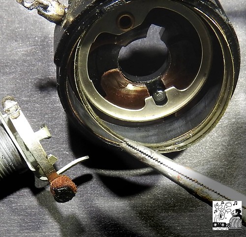 Mechanically, it appeared to work properly. So I tried a good, used 100K pot, and I got the same result as before. A third pot also gave the same result. This is the volume control. 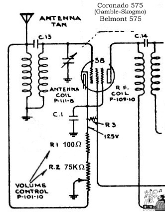  All electrolytics and paper caps were replaced. The remaining components and tubes were tested and replaced as needed. Continuity through all coils was checked. So, I must have done something wrong. I hope there's an obvious answer to this problem, and I'd appreciate any advice on the matter. Thanks, Henry
__________________
Winky Dink Damn the patina, Full speed ahead! 
|
|
#2
12-21-2017, 01:27 PM
|
||||
|
||||
|
That would appear to be normal operation. Volume is a misnomer here...It really is an RF input level control....As such capacitive and inductive qualities of the part will allow some RF leakage past it. Any missing shields in the set may render the control inoperable and leave you with a fixed volume output.
In all my TRF sets with 'volume' as a front end RF level adjustment the muting position or lack thereof depends on the strength of the station...Often the controls don't have a very linear response either....There was a reason later sets moved the 'volume' knob to the audio section.
__________________
Tom C. Zenith: The quality stays in EVEN after the name falls off! What I want. --> http://www.videokarma.org/showpost.p...62&postcount=4
|
|
#3
12-22-2017, 10:41 AM
|
|||
|
|||
|
Quote:
AVC sure was a godsend. 
|
|
#4
12-22-2017, 12:51 PM
|
||||
|
||||
|
Quote:
__________________
Tom C. Zenith: The quality stays in EVEN after the name falls off! What I want. --> http://www.videokarma.org/showpost.p...62&postcount=4
|
|
#5
12-22-2017, 09:20 PM
|
||||
|
||||
|
Quote:
 Hi Henry , Hi Henry , As a funny bit of side info here , in my radio experiments I learned that even though it may sound tempting , it's not a good idea to attempt to circumvent the original "volume control" with fixed resistors and to relocate the control to the first audio stage where we're most used to seeing it . Since as Tom and Dieseljeep said , it's more of a gain/tuning control than a volume control it must be adjusted for each different station received and what's good for one station won't be good for a different one . I have had success with leaving the front end circuit as designed , using the "volume control" more properly as a gain/tuning control , and then putting a "real" volume control in the first audio stage where it belongs . That way you can use the two original controls to tune the radio for best reception of each station and then adjust the volume to a tolerable level with the added in control .
|
| Audiokarma |
|
#6
12-23-2017, 10:24 AM
|
|||
|
|||
|
Quote:

|
|
#7
12-23-2017, 08:52 PM
|
||||
|
||||
|
Quote:
Exactly what I was thinking ! Now were this an "heirloom" set with the value of a Walton or similar of course I'd want to see it remain all original , warts & all , because that's how it was built . But where this isn't a set of any great monetary value , and because tinkering to make it better was a common thing back in the day when most radios were owned by technically minded/inclined folks , I'd say go for it .  I always found the lessons I remembered best were those where improvements like this were attempted . Most were successful , some weren't , but I'd say I learned something with each attempt that I may not have learned had I just left the set alone in it's stock configuration . I always found the lessons I remembered best were those where improvements like this were attempted . Most were successful , some weren't , but I'd say I learned something with each attempt that I may not have learned had I just left the set alone in it's stock configuration .
|
|
#8
01-01-2018, 11:27 PM
|
||||
|
||||
|
Thanks. I'll follow up on your suggestions. As for "breadboarding"--In this kind of situation I put little alligator clamps on all the leads until everything is satisfactory.
__________________
Winky Dink Damn the patina, Full speed ahead!
|
|
#9
01-03-2018, 02:35 AM
|
||||
|
||||
|
I hooked up both the RF control and the audio control yesterday, and everything worked as expected. Used a 500K pot for the audio, and had to drop R9 down to 100Kohms to get the plate voltage to where it was before. Today I put the components into their permanent positions, did a temporary hookup again, and now I get nothing audible. I've checked almost everything I can think of, so tomorrow I may put it back in it's original configuration and start over.
__________________
Winky Dink Damn the patina, Full speed ahead!
|
|
#10
01-03-2018, 11:44 AM
|
||||
|
||||
|
Have you checked your new volume control pot for leakage from the 3 terminals to the body of the pot? Sometimes a leaky pot will work great when breadboarded, but will short out the signal when grounded to the chassis...
jr
|
| Audiokarma |
|
#11
01-03-2018, 05:24 PM
|
||||
|
||||
|
Good call! I disconnected all the leads and sure enough, only 5 ohms from the sweep to the body. Hence, chassis-grounded. This pot was at least 60 years old, and it was the only one I had that was switched, had reasonable resistance, and a two-inch shaft. I have to go shopping. Thank you.
__________________
Winky Dink Damn the patina, Full speed ahead!
|
|
#13
01-03-2018, 08:41 PM
|
||||
|
||||
|
Hi Henry ,
Very happy to hear of your success with it ! Sure , we altered the circuit a bit , but we gained in the functionality arena just as hobbyists have been doing since before even that radio was new , good job !
|
|
#14
01-17-2018, 11:17 PM
|
||||
|
||||
|
Light at the End of the Tunnel
I try to live in accordance with the ancient proverb, "A journey of a single mile begins with a thousand blunders."
With just a few more blunders I'll be finished with the Coronado 575 journey. I installed the 1-Meg audio pot (switched) as advised. That went in the front volume control position. After much experimentation, I replaced the original RF pot with a 1-Kohm linear pot. I couldn't bring myself to drill holes in the cabinet, so it went to the back of the chassis. I also have a 20-ohm 25W line voltage dropper, and I added a toggle switch for that. I think this represents what I did:  One other change was that I had a 100K resistor for R9, and I changed that to the correct 250K. The final wiring (except for the toggle switch) looks like this:  The controls at the back of the chassis:  A quick before/after picture: 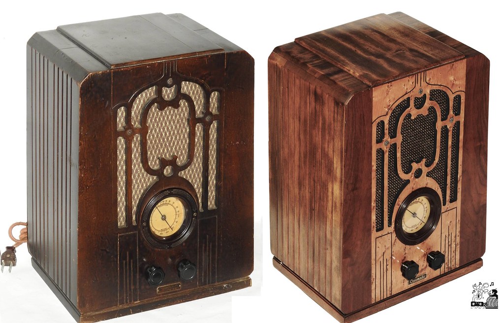 Everything works well. Very good reception of local stations with a 12-inch wire antenna, exceptionally sharp tuning at the precise frequencies on the dial, and no noise between stations. Unfortunately, the audio quality is not so good. I can only describe it as "buzzy." The distortion is what you would expect from a damaged speaker cone, but the speaker seems to be in perfect condition. Here's a link to a 15-second audio sample: https://flic.kr/p/22umN23 It sounds a bit worse in real life. Please let me know if you recognize what the problem might be. If anyone is interested, this is a link to a Flickr album with 15 additional photos of the restoration. https://flic.kr/s/aHsmbhh8ct
__________________
Winky Dink Damn the patina, Full speed ahead!
|
|
#15
01-18-2018, 12:10 AM
|
|||
|
|||
|
Regarding the sound, you might try disconnecting that auxiliary volume pot, and connecting C7 back per original. The pot is forming a voltage divider, reducing plate voltage on the 1st audio tube. That might be causing degraded audio (or might not).
|
| Audiokarma |
 |
|
|


 Hybrid Mode
