
|
|
|
#91
 01-20-2012, 09:54 PM
|
||||
|
||||
|
Hi Bob, I'm working on the exact same set right now, this has been one of the easiest sets to get working (you may remember it worked fine with no work done) while at the same time being one of the filthiest chassis.
I noticed the date on yours so I went and checked mine, it's stamped on the opposite end but there it was, Oct 13 1949, just eight days after yours, how many thousands of sets went out the door in between I can hardly guess. I'll be updating my thread soon with a video. 
|
|
#92
01-22-2012, 03:20 PM
|
||||
|
||||
|
This set is proving to be a bit of a challenge, but I'm getting there.
First, I did some voltage checking and found none in the vertical output circuit or brightness control. Turns out I forgot to install a 1.5K resistor. 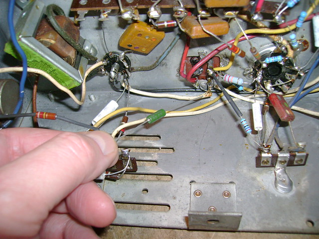 That got me a raster, but no video or sound. 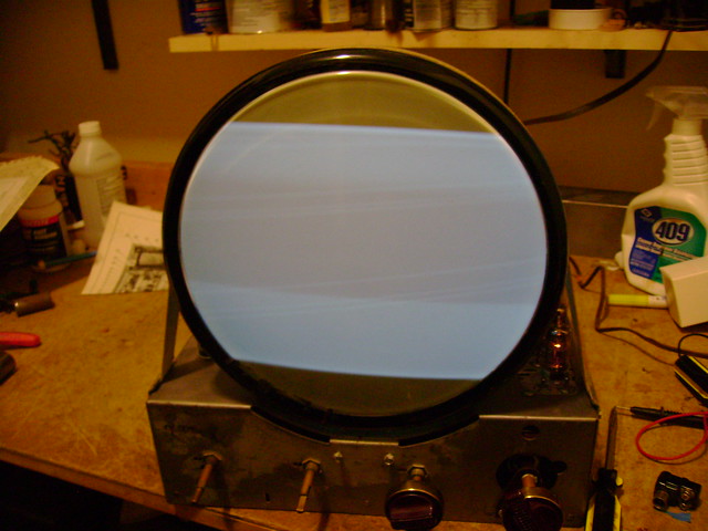 Next, I fired up a B&K 1077 and injected a signal into the first IF stage. That got me sound and a very unstable, off-center picture.  More investigating turned up a dirty 12AU7 sync tube socket, a bad 6J6 and 6AG5 in the tuner. That got a me a stable picture, good sound and a decent picture. Just one major issue remaining. The brightness control has a strange effect in the picture. The screen is dark for the 1st half on travel. Then a narrow window of visible picture. Then it blooms out of focus and gets dim. Seems like the grid bias voltage must be off, but they check out OK. Might also be the 10BP4 CRT. I recall it tested good back when I started this project, but I'll test it again. I'll try swapping it out with a known good one too. 
|
|
#93
01-22-2012, 05:10 PM
|
|||
|
|||
|
Sounds like the brightness control element has an open or dead spot in it.
|
|
#94
01-22-2012, 11:18 PM
|
||||
|
||||
|
Good idea, but it checks out OK. I perused the troubleshooting section in the Riders service info and found mention of picture blooming. They suggest it could by the picture tube or the 470K resistor in series with the HV lead.
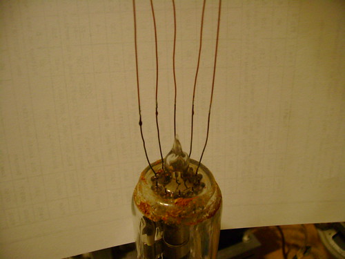
Well, I'm using a 5AXP4 test CRT that I know is good so time to check that resistor. I found it mounted right on the 1X2 rectifier socket. Briefly it measured around 500K then my DMM went to infinity and stayed there. I then tried a VTVM and got 30M !  I replaced it and viola! Plenty of brightness and no blooming  I recall reading that these resistors can go funky, but never experienced it before.  Just one problem left. While pulling the 10BP4 to install the 5AXP4, the base got hung up in the yoke and ripped out  Doesn't look too bad though. I'll try threading the leads back through and gluing the base on. I've done it before  
|
|
#95
01-22-2012, 11:44 PM
|
|||
|
|||
|
Yikes! Lucky none of the wires broke off where they enter the glass.

|
| Audiokarma |
|
#96
01-23-2012, 08:55 AM
|
|||
|
|||
|
One thing I have seen before and Bob, you may be the one that posted it, is that you can tack solder some longer pieces of wire on to the existing leads to assist in threading those wires into the correct pins. I have tried to do that with the leads the length that you show and it was almost impossible.
Please keep us posted...
|
|
#97
01-23-2012, 10:18 AM
|
||||
|
||||
|
If the set has an "iron wire" yoke, be careful with the CRT. The yokes seem to shrink down a bit in size and grab the CRT socket and pull it off when the CRT is removed. If possible, I would put the CRT back in without the base and install the base afterwards. My Admiral did the same thing but it had the copper seal on the CRT base and went to air shortly after. Also, be careful with the yoke. Being tight can make it easy to damage a winding (don't ask me how I know that....).
|
|
#98
01-23-2012, 11:31 AM
|
||||
|
||||
|
The yoke on my Admiral is tight too, warming them up a little with a heat gun or through operation sometimes makes it a whole lot easier to get the tube in/out.
|
|
#99
01-23-2012, 02:05 PM
|
||||
|
||||
|
Quote:
 Quote:
 Quote:
  Success! 
|
|
#100
01-23-2012, 05:40 PM
|
||||
|
||||
|
Looking good Bob
Those resistors again huh? They seem to be failing on a regular basis like capacitors now. Oh well at least it was that not the CRT. Cheers Glen
__________________
Visit my Vintage TV & Radio Page - http://nzvintagetvradio.blogspot.com/ My YouTube Link - http://www.youtube.com/user/glenz1975?feature=mhsn
|
| Audiokarma |
|
#101
01-23-2012, 06:42 PM
|
||||
|
||||
|
Yeah, dang resistors
 I replaced 75% or more in the last few sets I restored. I replaced 75% or more in the last few sets I restored.When I first started on this set, I ordered some 1/2 watt carbon composition resistors from Mouser with the intent of keeping it authentic as possible. Unfortunately, I was finding many of the new ones to be out of tolerance already! Always on the high side - just like the originals. I've also had a hard time finding 1 and 2 watt carbon comps. So, I switched to metal film and metal oxide. Not authentic, but very stable and reliable.
|
|
#102
01-23-2012, 09:17 PM
|
||||
|
||||
|
How did you get the extension wires to be soldered right on the end of the existing lead? I have tied them on the base and given them a few raps and then soldered the wire and the lead together but it's not easy getting them up into the sleve that way. I'm also wondering if a heat sink clip on the existing lead would be helpful at keeping the heat from reaching the metal glass connection
|
|
#103
01-23-2012, 11:45 PM
|
||||
|
||||
|
I tinned the extension wires and CRT leads. Then, butted the wire ends together and briefly touched my solder iron to the joint.
It's a lot easier if you first thread the extension wires through the base pins, then solder them to the CRT leads.
|
|
#104
01-24-2012, 12:24 AM
|
||||
|
||||
|
Quote:
|
|
#105
01-24-2012, 11:25 AM
|
||||
|
||||
|
Eric and Bob, if your sets were made only 8 days apart, how about subtracting serial numbers (assuming they are sequential) to see how many sets a week were made?
__________________
Reece Perfection is hard to reach with a screwdriver.
|
| Audiokarma |
 |
|
|


 Linear Mode

