
|
|
|
#16
 09-09-2008, 05:01 PM
|
|||
|
|||
|
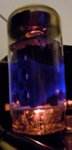
It's a Christmas Miracle!
PICTURES! 
|
|
#17
09-09-2008, 05:38 PM
|
||||
|
||||
|
Do I see the French word AVIS (meaning warning) on the metal cover in the upper
right corner? This could be a Canadian made set, or one marketed under the same model number in Canada. As was expected, this is a series string set, meaning that the designers did away with a power transformer, and that most tube heaters are wired in series. If any of those heaters fails, the tubes won't light up, but you already checked that. If you undertake removing the chassis (a step that is almost mandatory to do some serious repairs such as replacing the filter capacitors), be very careful with the following: the picture tube base may have unglued from the glass, and pulling the socket to remove it could just tear the base away, break the fine wires and possibly destroy the tube. Always make sure that connections between the various parts of the system are properly undone before you pull out anything. Series string sets are somewhat trickier to service than those with a transformer, but they are capable of good performance. Good luck. P.S.: If this is indeed a Canadian market set, give me until next Monday to find a schematic for you. I might have it. Last edited by electroking; 09-09-2008 at 05:41 PM. Reason: added a note
|
|
#18
09-09-2008, 05:43 PM
|
|||
|
|||
|
Actually your right. The Tv was made in Montreal apparently. I thought that was pretty cool.
If you could find a schem that would be great...Thanks Rudy
|
|
#19
09-10-2008, 01:41 PM
|
|||
|
|||
|
I've taken the set out of the box to get a better look at it. And have some more pictures of some parts. Like one part that I think is the "sand resistor" (only measured 25 ohms) and it was physically chipped. Also I found one of the only looking possibly burnt capacitors. It is conneceted to the 1x2b and just looked charred black near the bottom. Check it out. Is this a good spot to start.?
I've also been checking random resisitors and all of ones near the burnt cap. They all seem OK....not perfect but close enough to what they should be. Are the resistors normally Ok in older TV's? Now to test for the B+ supply for the tubes what should I do. Plug it in with a voltmeter hooked up to the larger capacitors. Or how? should I go about this. With my little tube amps this was fine But they don't make voltages in the quadrupal digits.
|
|
#20
09-10-2008, 01:44 PM
|
||||
|
||||
|
The B+ in those sets runs somewhere between 375 and 500v. YOu need some service literature like a sams photofact to tell you what the voltage measurements should be.
Just measure between the terminals of the filter caps and ground. Look for excessive AC voltages at the caps too. That usually indicates a leaky or open capacitor.
__________________
Jordan
|
| Audiokarma |
|
#21
09-10-2008, 02:22 PM
|
||||
|
||||
|
On a "dead" set--i.e. no picture and no hum in the speaker, but tubes all lit, it is usually failed B+ off those two blue selenium diodes. With the set unplugged arrange an alligator clip hook up at one of the twist-lok tabs where the common negative should be. It might be directly connected to the chassis pan, but sometimes a maker will get weird and isolate the pan. Clip the other end of the alligator jumper to the negative test lead of your meter, and set it so that it can read up to 500-600volts. Plug in the set and fire it up, and you can quickly ascertain whether or not there is B+ present at the voltage doubler circuit comprised of the two blue rectifiers. It'll be around 300 volts usually.
If there is voltage present then listen to the "doghouse" of the set and--if you have young and healthy ears--determine if you can hear a dog-whistle high pitched sound indicating horizontal sweep. If there is then you may see some boosted B+ sweep-signal-derived off the damper tube and a winding of the flyback coil--about 400 to 500 volts. If you are not hearing the 15.75KHz whistle then have a quick look at the anode of the horizontal output tube to see if its plates might be turning red from lack of drive-induced negative grid bias. Pull the plug if it is, or lose the tube, or perhaps blow a fuse. In fact staring at the plate of the 12BQ6 should be the first thing you do after powering up; if there is no drive the tube can go up quickly. If there is no boosted B+ then in some sets there is no audio either, as the sound output tube draws from boosted B+ and "moonlights" as a voltage regulator, feeding about 130 volts off its cathode to such as the IF stages and the tuner. Thus there will be little or no action from the set at all. You may already know these things, but.... Left hand in pocket is a good rule. Places not to go with your voltmeter test prod are anywhere within the "doghouse" (high voltage cage), the heavy lead running to the anode well on the back of the picture tube, the anode cap of the horizontal output tube and the anode pin of the vertical output tube. Also--like the rule about loaded/unloaded guns--there is no such thing as a fully-discharged kinescope (picture tube)!!!! They make a very efficient capacitor, and can hold a charge for decades. AMHIK.
|
|
#22
09-10-2008, 02:39 PM
|
|||
|
|||
|
There is no hum Or red glowing tubes that are being overloaded i'm almost sure. The set literally gives no action other than tubes all glowing red. I will go test the selenium rectifier momentarily to see if it is truly failed.
And THANK YOU for the warning about the DOGHOUSE. I was poking around in there two days ago :S. Not for voltages but just to test the tube. Thank God I was being careful. ......and all you guys Thanks I was gonna just strip this thing when I found it, and probobly would have. But now that I know theres hope I have this dieing urge to play my nintendo and atari on it :P
|
|
#23
09-10-2008, 03:04 PM
|
|||
|
|||
|
There DEAD, there really dead.
From the chassis(witch the selenium rectifier's ground was directly soldered to) The possitive side of the selenium rect shows a peak voltage of 30 dc. The other one shows a whopping 5. So is this where the B+ originates from? DO the other B+ just get stepped up from the volatges made in the selen. rect? So I'm guessing I need that for sure. But what will I be replacing it with? Another selnium one that's the same. Or is there a better new diode used when replacing these old ones cause I don't know first hand. This is also my first TV repair job, and I'm lovin it. Rudy
|
|
#24
09-10-2008, 08:21 PM
|
|||
|
|||
|
Alright I have 2 or possibly more 6a2 diodes. I think they are rated at 6amps 200 volts. And I know I built a 250 volt power supply from them. Would this be sufficient as a replacement. Cause from what I read the selenium are much larger than the silicon ones. So maybe these two guys would work? They are about 1 cm long and .7 cm in diameter.
Like I said I have no money so I wanna do anything I can with what I've got. (.91 cm x .91 cm actually) And If I do have more than one can I double them up or put them in series to increase the voltage they can handle? I know it can be done with a cap And one more question. The caps in this TV do you think there full of PBCs. Or is there no doubt they are
|
|
#25
09-10-2008, 11:01 PM
|
||||
|
||||
|
Those selenium rectifiers are probably rated maybe 1/2 amp. Voltage I'm not so sure about though. Probably you'd want something to handle a little more than 200. I used 1N4007's to replace the selenum stacks in my Philco.
PCBs are usually found in oils. THose caps are mostly paper and foil. The electrolytics have some sort of borate in them usually, no PCBs. THe rest are dry (well, other than the water they've sucked up over the last half century) Handy tip for testing the HV lead. Use one of those compact flourescent lamps or even a small flourescent tube held near the HV wire. If it glows, you have high voltage. Don't get your fingers too close to this, the HV lead probably runs 15,000 volts or so.
__________________
Random bits of stuff in the collection: Yamaha YP-D4 turntable with B&O MMC 10E cart Allied 495 receiver 2 Magnavox amps, AMP150 and an AMP178, currently under the knife. Onkyo TX-4500 Onkyo Radian III speakers
|
| Audiokarma |
|
#26
09-11-2008, 12:53 AM
|
|||
|
|||
|
That's a handy trick I must say.
I guess i'll go grab a diode tomorrow. I'm sure I can scrounge 50 cents. Then do you guys think I should give it a whirl..or no?
|
|
#27
09-11-2008, 08:19 AM
|
||||
|
||||
|
Quote:
Make sure you get the polarity correct on all those diodes and capacitors....unless you like extreme excitement....
|
|
#29
09-11-2008, 12:22 PM
|
|||
|
|||
|
Thank you wa2ise,
You made me remember I had an old fried superbrain charger. Full of diodes. Turns out they are 6a10 much like the other ones I had but rated for 1000 Volts! 6 amps I'm gonna go put them in now
|
|
#30
09-11-2008, 01:31 PM
|
|||
|
|||
|
so the diodes are in. I also left the old ones in but disconneceted them from the circuit. Looks cool.
And if I am correct I wanted the stripe of the diode (cathode) To be connecetd to the + side of the capacitor? Well I'm gonna test it. After I build a bombshelter around it. If you don't hear from me again.....Tubes Rule! :P
|
| Audiokarma |
 |
|
|


 Linear Mode

