
|
|
|
#1
 04-20-2014, 11:08 AM
|
||||
|
||||
|
Predicta Stuff
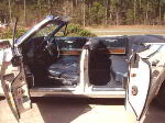
OK, finally go the Princess and found a few issues right away....
Bad on/off switch? No problem....just plug er in when you want to watch...... Both top hats are open...... and what the heck is this wire stuffed into the vid tube socket? Surely not factory? Perhaps an attempt to fix a bad board trace? 
|
|
#3
04-20-2014, 12:10 PM
|
||||
|
||||
|
Yes, it sure looks like a repair to me. Broken pins is a common problem in these tube sockets.
|
|
#4
04-20-2014, 04:39 PM
|
||||
|
||||
|
I had one heck of a time getting that tube out with that wire stuck in there...had to gently pry on the base with a plastic screwdriver.....someone really didn't want to pop that board and fix the darn socket! ...Who knows what other joys await......
 at least this is encouraging....351 ohms, and yes, that is the bed of my pickup.....we'll be back in the shop in a day or two... at least this is encouraging....351 ohms, and yes, that is the bed of my pickup.....we'll be back in the shop in a day or two...
|
|
#6
05-04-2014, 01:16 PM
|
||||
|
||||
|
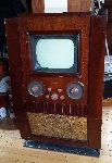
Waiting on the rest of my electros to finish the re-cap, but here is my K5. The jury is still out on my pluggable pcb wires as the tube socket connectors don't hold up well to plugging/unplugging. I'm still going to try some different connectors to see if all this is worth the effort. The board can be changed out pretty quickly, once the connectors are in place.....
|
|
#8
05-04-2014, 09:11 PM
|
||||
|
||||
|
I don't think I'd go that far with this "pluggable" thing. If a K-net is bad, you replace it....end of story. Making the entire board more accessible with all the possible parts to fail, makes at least some sense....I guess if you were to become a "Predicta Specialist" and do nothing but those sets, you could justify some more re-design along those lines. Heck, I think it would be cool to bundle all the loose wires into chassis and board harnesses, and put in 1 male and 1 female 30 contact connector! Talk about easy to service! But would I do it for 1 set?

|
|
#9
05-17-2014, 09:06 PM
|
||||
|
||||
|
1st power up
Finally got the rest of my electros installed, and hooked up the variac for a power up. No ammeter hookup, so watched carefully...at about 75-80Vac on the line, I started to get some audio, so dialed up to 90, and noticed the plate of the 6DA4 damper tube starting to glow a bit red, so I shut down, and did some checking. The flyback was 1st on the list, but all the resistance readings are right on with the expected values. Tube tested the 1B3GT, and not great output, but in the low green, and no apparent shorts. I had already replaced the resistor to the HV of the CRT, and all the associated caps have been replaced, and resistors nearby checked as well.. I also tried with the yoke plug disconnected as well...same result. I checked B+ at 70V line input and was getting about 225V, so that seems about right. (no raster through any of this)
Seeking sage advise as to Where to go from here?? (Could I do any meaningful voltage checks with the damper tube pulled??) VOT ?? Last edited by bonanzaman; 05-17-2014 at 09:24 PM. Reason: late thought
|
|
#10
05-17-2014, 10:04 PM
|
||||
|
||||
|
Have you checked the damper for emission/shorts? Also how close is the horizontal oscillator waveform to that in the service lit?
__________________
Tom C. Zenith: The quality stays in EVEN after the name falls off! What I want. --> http://www.videokarma.org/showpost.p...62&postcount=4
|
| Audiokarma |
|
#11
05-17-2014, 10:27 PM
|
||||
|
||||
|
Well, I just checked the tube and it had a short....I don't think it did when I checked before. Popped another in and got up to full line voltage (audio, but still no raster)...ran for maybe 30 sec or so, and the plate on the replacement started glowing again! Short somewhere perhaps? I had a gut feeling I was going to need a scope before I was through with this set.....can't check any waveforms at this point!
|
|
#12
05-18-2014, 06:10 PM
|
||||
|
||||
|
Well, in the absence of any further advice (or a scope, for that matter!), I made an executive decision, and pulled the damper tube to do some voltage checks. The hor osc tube's pins all have what seems to be in the ballpark....within 10-15% of what's listed on the Philco factory diagram. Also the sync sep/vid out.looks close....the plate and grid of the vid output half are about 30% high, however. But the real stinker is the Vert Osc/Output tube voltages:
pin 9 cathode of the output side sb 15-18v measured 1.6v pin 6 plate of osc side sb 115-130v measured 60v pin 8 cath of osc side sb 7.5-10v measured 1.4v Finally, the 400v boost is measuring only 187v ! Not sure if this is an issue with the damper tube pulled. B+ on the other hand, seems a healthy 316V. I fear the flyback may be the culprit here, even though the resistance checks are all spot on. Can anyone surmise a direction to look further from this, ....I'd be grateful for it! Last edited by bonanzaman; 05-18-2014 at 06:49 PM.
|
|
#13
05-18-2014, 09:55 PM
|
||||
|
||||
|
Yeah, you won't get full boost with the damper out. The vertical circuit uses some of that boost voltage so that's probably why they're low.
I suspect something with the horizontal oscillator or drive. I've yet a to find a bad flyback ever, so that'd be low on my list. Not saying it can't happen, but replacements are very hard to find so try to eliminate all other possibilities first.
|
|
#14
05-19-2014, 09:18 AM
|
||||
|
||||
|
Damper tube meltdown
OK, thanks, Bob....so I understand that if the osc is not running, or is off freq, then no HV gets generated, but would a failure of the K7, or even K6 cause the damper tube to roast? I ask because those are the only components I am unable to check directly. I have, of course replaced all the board caps, and checked (& replaced a few) all the resistors....well 98% of em'.... Or am I looking for something more dramatic, like shorted wire or such? Sorry for the questions, but I am still trying to learn this video stuff!
I have an offer in on a 465 Tektronics, so if that happens I'll have another tool for the diagnostic arsenal!.....gotta re-learn it though, the last scope I owned was an Eico 5" in about 1964!
|
|
#15
05-19-2014, 01:57 PM
|
||||
|
||||
|
OK, so I pulled the K7 network, rebuilt it and re-installed, not supposing for a minute, that anything would change, but on power up, I was pleased to see that the damper tube was not overheating.......however, now the overload seems to have shifted to the HO tube! Purple discharge, and dull red glow in the plate...sheesh, what's happening here???? Still no raster/HV.
|
| Audiokarma |
 |
|
|


 Linear Mode

