
|
|
|
#31
 12-03-2010, 11:29 AM
|
||||
|
||||
|
I've seen that 6AQ5 cause lots of odd problems in convergence issues if it is gassy.
Your set will be a real sweetie when you get done. 
|
|
#32
12-04-2010, 12:35 PM
|
||||
|
||||
|
I don't think it's gassy or anything, just reads weak on the tube tester.
The fix is in now anyway, new tubes from AES have arrived!  NOS RCA 6AQ5, GE 3A3, Dumont/GE 6AU4 dampers, and a nice pair of Amperex 6CB5A's with black plates. Should make for a stout high voltage section. 
__________________
Evolution... 
|
|
#33
12-17-2010, 05:36 PM
|
||||
|
||||
|
Just found out after some resistance checks that the screen/grid control pots are bad, with some intermittent places on the carbon track. Been looking around on the net for replacements, but all I'm finding are crappy quality ones that probably wouldn't last long considering they have boost voltage running through them. Anyone got a good lead on a quality replacement? I'm looking for 5 1-meg linear pots total, preferably with plastic shafts.
__________________
Evolution...
|
|
#34
12-17-2010, 06:11 PM
|
||||
|
||||
|
|
|
#36
12-17-2010, 11:32 PM
|
||||
|
||||
|
Quote:
Trying to help,
__________________
Brian USN RET (Avionics / Cal) CET- Consumer Repair and Avionics ('88) "Capacitor Cosmetologist since '79" When fuses go to work, they quit!
|
|
#37
12-18-2010, 10:09 AM
|
||||
|
||||
|
Quote:
They are twist-lock, with a tab on either side of the plastic shaft. RCA part number on the back is 972137-1, but I'm not really concerned about brand. I just want something that's not going to break 2 months from now, like most of the Chinese stuff is likely to do.
__________________
Evolution...
|
|
#38
12-20-2010, 12:03 AM
|
||||
|
||||
|
Crisis averted for now, I was able to take each one apart and clean them with contact spray. No idea if it will last, but they seem to be working for now.
__________________
Evolution...
|
|
#39
12-23-2010, 05:39 PM
|
||||
|
||||
|
OK, latest work has revealed the following:
I thought the horizontal osc was working just fine, but when supplied with a signal with my NTSC gen it refused to lock at the correct frequency. I figured I had some more bad caps, so I made a trip to Chesters. After replacing the rest of the old micas, the problem persisted. I then read out the voltages in the circuit, and every single one was 60 high! I then had a look at the power supply, where I confirmed that B+ was indeed 60 high (440 vs 385). I'm guessing that selenium rectifiers were grossly ineffecient, because there's no way 5 extra input volts equals an increase that large. Short of always running it on a variac or bucking transformer, I guess I'm looking at dropping it with resistors. So the question becomes do I get a huge high power wirewound, or insert 2 smaller ones right before the rectifiers?
__________________
Evolution...
|
|
#40
12-24-2010, 02:16 PM
|
||||
|
||||
|
You need to get bypass the selenium stacks with silicon diodes. Leave the selenium stacks in place for looks, but leave them disconnected.
I don't understand why you would have High B+ using the selenium stacks because they normally will be inefficient and produce lower voltages than the silicon diodes. AFter installation of the silicon diodes I use some 20 watt wirewounds to reduce the B+ to the correct specified voltage in my sets. I use a 20 watt power rheostat to determin the correct value of fixed resistor use.
__________________
Vacuum tubes are used in Wisconsin to help heat your house. New Web Site under developement ME http://AntiqueTvGuy.com
|
| Audiokarma |
|
#41
12-24-2010, 02:46 PM
|
||||
|
||||
|
The seleniums have long since been replaced by a pair of obligatory RCA 'tophat' diodes, sorry if that wasn't clear. I'm trying to correct B+ as a result, since it's now 60 volts higher than it should be. I've understand dropping resistors in the 150-200 ohm range should do the trick, I'll find exactly what value tomorrow or the next day.
__________________
Evolution...
|
|
#42
12-25-2010, 01:57 PM
|
||||
|
||||
|
OK here is what to do.
First, measure the current on the B+ line you want to place the dropping resistor into. Now using Ohm's law solve for R. R=E/I ..... Plug in the current (I) in AMPS and the voltage you want to drop (E) in volts (60) and the solve for R (the resistance needed). So lets assume 500ma is the measured current, the equation would look like this: R=60volts /.5 Amps so R=120 ohms Then to figure out how many watts the resistor needs to be use P=IE Where P the power in watts = the current (I) in AMPS times the voltage drop across the resistor E (which in this case is 60 volts) Lets assume the following for the Power equation P (watts) = IE so P= .5 Amps * 60 volts Therefore P=30 watts No guesswork needed if you know the current flowing and the voltage drop needed. The value of the resistance will not likely be a standard value, so get one of those tubular ceramic types with the adjustable slider band so you can adjust to the needed value. Good Luck!
__________________
Vacuum tubes are used in Wisconsin to help heat your house. New Web Site under developement ME http://AntiqueTvGuy.com Last edited by ohohyodafarted; 12-25-2010 at 02:02 PM.
|
|
#43
12-25-2010, 02:23 PM
|
||||
|
||||
|
Quote:
jr
|
|
#44
01-10-2011, 02:41 PM
|
||||
|
||||
|
Quote:
Exactly what I did, final value ended up being 75 ohms. My brother ended up having a 30-watt Ohmite resistor, I mounted it on a piece of angle aluminum and fixed that onto the removable plate that bolts to the HV cage. B+ is now a perfect 385, while the other line is slightly high at 292 ish. I think that will be just fine.
__________________
Evolution...
|
|
#45
01-10-2011, 04:21 PM
|
||||
|
||||
|
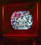
Important update: I have something on screen!
I ended up having to slightly rewire the power supply because of the B+ resistor I installed. At first I had some lines crossed, and that was causing a strange hump (like the negative going half of a sine wave) to appear in the vertical scanning waveform. It also screwed with the sync circuits, causing a no lock situation for both vert and horizontal. After fixing the B+ supply, the voltages fell perfectly in line and the scanning waveforms looked perfect as well as having perfect sync. I had been injecting a signal into the video amp tube, because I wasn't sure of the condition of the tuner. Now that I have things in order though, I hooked the tuner back up and it works just fine.  Color is even trying to work, but it's not quite there. I think I'll probably end up having to do a full on chroma alignment, even though it pains me to think about it. Last time (on the CTC-7), it took like a weeks worth of fiddling to get things to fall into place.  Here's a pic of what I have thus far:
__________________
Evolution...
|
| Audiokarma |
 |
| Thread Tools | |
| Display Modes | |
|
|


 Linear Mode

