
|
|
|
#1
 02-17-2003, 07:12 PM
|
||||
|
||||
|
Problem with the Sonora
Ok, I've replaced all the paper caps in this thing as well as the Flyback.
At this point I have a picture but it is split down the middle, I can scoot it over to one side with the horiz hold control but it is really unstable at that point. Horizontal drive, linearity and width slugs seem to be working? Is this a problem with the horiz frequency or the phasing? Tubes have been checked and subbed but I haven't replaced any of the big Lytics at this point. Eric 
|
|
#2
02-17-2003, 07:31 PM
|
|||
|
|||
|
Eric,
Do you have two complete pictures side-by-side, with a bar in the middle? If so, the horizontal oscillator is running at exactly one-half frequency (7,867 cps vs. 15,734). If you have only one complete picture with the left and right halves reversed, it is a phasing problem. Is this a synchroguide horizontal oscillator? If so, it may need the stabilizer coil adjusted with a scope. The synchroguide system uses a single 6SN7 tube, has no AFC diodes, and separate slugs on each end of the oscillator transformer can. The slug on the bottom (under chassis) is the stabilizer adjustment. The top slug is the oscillator frequency adjustment.
|
|
#3
02-17-2003, 08:33 PM
|
||||
|
||||
|
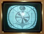
Hi Bill, it looks like one picture reversed and split.
I posted the schematic here: http://www.vintagetvsets.com/images/sams1.jpg http://www.vintagetvsets.com/images/sams2.jpg That is the entire Sams for this set, one sheet, no pictures or parts diagrams! It uses a 6SN7 oscillator but I don't think it is a synchroguide system as there is only one slug for the frequency. At first I was having problems getting the horizontal to lock in at all, I had about 4 images side by side. I found resistor R90 had increased from 220k to 320k so I added another resistor across it to bring it back down. That helped but it still was out of range so I added another .0033 cap across the horiz frequency coil (it calls for a .0039 and I only had a .0033) this enabled me to get it to lock in with only one split picture. I then went back and replaced those caps with a .001 and a .003 in parallel for a total of .0043 across the coil, I figure this is close enough but i still have the split. The horizontal phase det seems to be split between the 6T8 and the 6AL5 ? I did find that pin 5 of the 6AL5 has 10v where it's supposed to be 3.2v. Both tubes have been subbed as has the 6SN7. Eric
|
|
#4
02-17-2003, 09:01 PM
|
||||
|
||||
|
Picture
Here's a picture of the problem
|
|
#5
02-17-2003, 10:22 PM
|
|||
|
|||
|
Eric,
Aha! You have a problem in the timing of when the sync circuit starts the horizontal line sweep. It is locking up the horizontal oscillator halway along the sawtooth instead at the beginning of it, or if you wish, half of 63 uSec early or late to the video signal. What you are seeing is the horizontal blanking interval. If you adjust the vertical hold so that the vertical interval also appears on the screen you will have what the industry calls a 'Cross Pulse monitor'.  I have an idea. Since the damper tube starts to conduct in this region of the sawtooth I wonder if a pulse from start of damper conduction is somehow appearing on the plate of the sync detector or the H. oscillator tube. Might be from an open bypass capacitor? I have an idea. Since the damper tube starts to conduct in this region of the sawtooth I wonder if a pulse from start of damper conduction is somehow appearing on the plate of the sync detector or the H. oscillator tube. Might be from an open bypass capacitor?I'll have a look in my RCA red pic-to-guides and see what Meagher has to say. In answer to your question, the H. frequency is spot on, it is the phasing that is way off. Rob
|
| Audiokarma |
|
#6
02-17-2003, 11:48 PM
|
|||
|
|||
|
Eric,
That is not a synchroguide, it's a diode phase detector afc circuit. In later models those diodes are solid state, and usually one is bad when this kind of problem occurs. Since you have checked the tubes, it has to be something else, but in the area between the sync separator and the H oscillator. I am suspecting C65, C66, C67, C68, C69, C70, & R76, R77, R78, R79, R80, R81, R82, R83, & R84. You may have already replaced some of those caps. A pulse from the flyback is taken off at the width control and is fed back through several components to the 6AL5 phase detector diode cathode & the 6T8 diode plate. Sync pulses are taken off at the junction of R77 & R78 through C65 to the 6T8 phase detector plate. Sync is also supplied from the 12AU7 sync sep cathode thru C66 to the 6AL5 cathode. The phase detector circuit compares the flyback pulses to the incoming sync pulses, and develops a correction signal if there is a timing difference, which is supplied to the oscillator through R63, R64, & C69. So, there are four paths to be concerned with: the two sync paths, the flyback pulse path, and the correction path. I'll bet the problem is that one of these four signals is missing, or low in amplitude. A scope should locate the problem in short order. Good luck! 
Last edited by wvsaz; 02-18-2003 at 12:02 AM.
|
|
#7
02-18-2003, 10:35 AM
|
||||
|
||||
|
Thank you Bill,
I will get the Scope out tonight after work and see if I can figure out what's going on. Eric
|
|
#8
02-18-2003, 02:32 PM
|
|||
|
|||
|
Eric,
I just had an idea that might be worth checking first. You replaced the flyback with one that was a "mirror image" of the original, so you had to resolder some wires. Look on the schematic at the bottom winding of the flyback, the one with the width control (L15) connected across it. One end is grounded, and the other end goes back to the phase detector circuit. If the leads from this winding somehow became reversed, the horizontal output stage & width control would still work normally. However, the pulse going to the phase detector would be reversed in polarity, and would drive that circuit crazy! Since this was not an actual "exact replacement" transformer, the leads from that winding may have already been reversed at the terminals when you got it!  Just a thought. Just a thought.
Last edited by wvsaz; 02-18-2003 at 02:42 PM.
|
|
#9
02-18-2003, 09:47 PM
|
||||
|
||||
|
Yes!!!!!!!!
Bill, your a genius!
 I switched the wires around and it works!! I had wondered if the fly might have been different somehow but I would never have figured that out! Thank you!
|
 |
|
|


 Linear Mode

