
|
|
|
#32
 12-29-2011, 01:29 AM
|
||||
|
||||
|
Progress & Questions
Okay! I'll start with the questions....
Is it necessary to replace the seleniums before a power up? And to those whom have installed 1N4007s in place of the seleniums what if any added series resistance value did you use? And to those who have used newer CRT types than the 21AXP (Nick...) how did you connect the HV button on the CRT to the HV connector on the HV cage? I've got my fingers crossed that this can be safely done without cutting the HV plug off the plastic CRT cover as I entertain the hope of someday having a good 21AXP22 to install...... Also which tubes are supposed to have shields on them? As for progress...... I've disconnected the Doubler and B+ from the transformer and done a power up to confirm that the power xfmr is still good. The fillaments lit so it would seem that my power transformer is still good.   I'm presently variacing the set with only the doubler caps and seleniums connected to the B+ winding on the xfmr (I unsoldered the B+ lines) so I can reform 3 of the lytics and check the seleniums under power simultaneously. I've been continuing to clean the chassis as well. I thoroughly cleaned the inside HV cage including removing the HV rectifier cup for a cleaning. The place where the HV rectifier cap connects to the fly was missing most of it's wax and kinda loose so I took some dripped wax and built up the wax around it for added support. I was concerned that the the connection on that lead was open so I checked the resistance between it and the HOT cap lead and got within 10% of what sam's lists that resistance value to be which is a good sign.  I also for the briefest of moments touched the barrel of my soldering iron to the wax on the HV winding of the fly to melt the outer layer of wax in order to fill in some small cracks in the wax coating. I also for the briefest of moments touched the barrel of my soldering iron to the wax on the HV winding of the fly to melt the outer layer of wax in order to fill in some small cracks in the wax coating.I replaced the HV cage lytics as well. I replaced the 20uF 25V caps with 22uF 250V replacements, and the 5uF 25V with two 2.2uF 63V Radio Shack "how the heck can new caps have some ESR???" specials connected in parallel (I'll likely change these turkeys later for a better part). Here are some pictures.....More can be found in the link from the first post in this thread....            EDIT: yes the title is a me using a word play on the title of the opera "The Barber of Seville" as a pun....Glad one a' ya uncultured swine (I'm joking here) gets it. And NO I'm not a fan of Opera (classical aint bad, and I like most popular music from the 50's to the 80's, but Big Band/Swing is what I really LOVE).
__________________
Tom C. Zenith: The quality stays in EVEN after the name falls off! What I want. --> http://www.videokarma.org/showpost.p...62&postcount=4 Last edited by Electronic M; 12-29-2011 at 01:41 AM. Reason: Add something. 
|
|
#33
12-29-2011, 10:46 AM
|
||||
|
||||
|
Quote:
My CTC-4 came with modern silicon rectifiers already in it, I just run it a little low on input voltage and read B+ till it's correct. I toyed with resistors before, but they dissipate a ton of heat. Quote:
Here's an Ebay link, but $70 seems pretty steep for just the wire: http://www.ebay.com/itm/Tektronix-pn...item43ac0df518 Perhaps you can cannibalize a broken scope? Quote:
Just the ones that have grounding fingers attached to the chassis.
__________________
Evolution... 
|
|
#34
12-29-2011, 12:44 PM
|
||||
|
||||
|
I used to have a busted Tektronix scope....sh!t now I wish I had not chucked it into a radio club swap meet donation auction!
So basically all tubes except the the 6AQ5s, octals, and what is inside the HV cage need to have shields. Right?
__________________
Tom C. Zenith: The quality stays in EVEN after the name falls off! What I want. --> http://www.videokarma.org/showpost.p...62&postcount=4
|
|
#36
01-01-2012, 06:27 PM
|
||||
|
||||
|
Went to Chester's yesterday and got the remaining tubes and some lytics I needed.
Yesterday night I brought it up on my variac with the plate lead of the HOT and the damper tube unpluged, and was able to tune in good sound from my signal source, and confirm that the H osc. is working properly. I didn't try for a raster as the screen voltage on the HOT was too low for me to justify connecting the HOT and damper. Also the vertical osc. appears to be dead. I haven't had enough time to do much today so far, but do know that an open 11K resistor is to blame for the low screen voltage. I may not have an exact replacement for that resistor, and will likely have to do some scrounging later on. I bought some HV lead at Chester's and striped, folded, and soldered a long section of wire at the end so that it has a decent mesh with the HV connector. Not the best, but it should be good for a test later on. I'm very happy that the RF and IF seem to be working!  With luck I may soon have a raster.
__________________
Tom C. Zenith: The quality stays in EVEN after the name falls off! What I want. --> http://www.videokarma.org/showpost.p...62&postcount=4
|
|
#37
01-02-2012, 02:03 AM
|
||||
|
||||
|
We have got a RASTER!!
 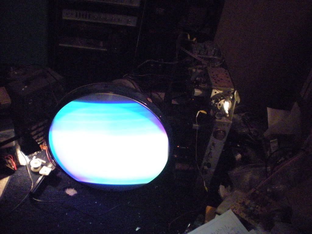 About an hour ago I finished preparations and proceeded to do a full power up including the FULL horizontal stage. The best replacement for the bad 11K ohm 10W screen resistor for the HOT I could find was a 10K 7W, but I figured that it would last long enough for a full test, and I was right. After putting the sub in with the top lead of the HOT still disconnected I read 110V. Sam's calls for 160V at the screen. I also decided not to sweat over not having the vertical osc. running the other day as I noticed that the plate of that tube gets it's voltage from the boost line, and thus would not work unless I went ahead and connected the flyback up to the HOT and damper. The HV was only 15 KV (and falling) on the second test (I was too excited on the first brief power up to read the meeter). I figure that with low HOT screen grid voltage and all new tubes across the board that this is not too bad for a first power up. I did not have sound during the test which I attribute to me messing with the tuner setting earlier in the day. This set may possibly have video for all I know. This was the last task of the night. I'll see if I can do more tomorrow.
__________________
Tom C. Zenith: The quality stays in EVEN after the name falls off! What I want. --> http://www.videokarma.org/showpost.p...62&postcount=4
|
|
#38
01-02-2012, 02:07 AM
|
||||
|
||||
|
Congrats! It;s always a good feeling when the raster appears for the first time.
__________________
"It's a mad mad mad mad world" !! http://www.youtube.com/user/mwstaton64?feature=mhee
|
|
#39
01-02-2012, 03:27 PM
|
||||
|
||||
|
We have now got VIDEO and sound!
      Well I got my signal issue sorted and did another power up. This time at the suggestion of a member of ARF to my thread there; I meetered the screen of the horizontal with the plate lead of the HOT connected, and I got 150V. This is close enough to the 160V sam's calls for that I will not loose sleep over the resistor that is in there(at least for now). When I first powered it up with signal the video was so weak I almost missed it. I did see it though and synched up the horizontal and vertical. Even with the contrast maxed the video was really weak, and the deflection would not keep synch so my mind went straight to AGC. The control was near max already and maxing it did not yield enough improvement so I started jiggling tubes in their sockets and it was the second IF tube that fixed it. In fact after shifting that tube to a better position the signal was overloading the set. A quick readjust of the AGC and all was well (except for the dead color circuits and a some other bugs). The HV stayed at about 20KV this time and adjusting the regulator would only reduce it. After about an hour of operation the fly was pretty warm. I think it is about time for me to read and preform the Sam's horizontal adjustment procedure on this set.... The screen controls were sticky and the red is stuck. Between this and the dirty tube sockets I believe that it is time to get some DeOxit and start cleaning controls and contacts. WOO HOO! Just a bit more and it will be working like new again!
__________________
Tom C. Zenith: The quality stays in EVEN after the name falls off! What I want. --> http://www.videokarma.org/showpost.p...62&postcount=4
|
|
#40
01-02-2012, 03:39 PM
|
||||
|
||||
|
Good job, Tom!!!
I knew it was a good chassis the minute I laid eyes on it, all it needed was the attention of a good tech to bring it out of hibernation. Image still looks like hell, but you can tell everything's trying to work. Worry about the color section last, for now you need to turn your attention to all the pots on the convergence panel. I promise every last one will end up having something wrong with it, and you'll never get it adjusted right without them being good. So fix all the bad pots, then move on to other sections.
__________________
Evolution...
|
| Audiokarma |
|
#42
01-03-2012, 01:58 PM
|
||||
|
||||
|
Thanks!
The main reason I could do this so fast is that I had most of the right values of paper caps on hand, and enough extra wrong values to make accurate enough (I fudged some values in the audio stages because those stages are not critical, and I rarely use the sound on my sets) replacements for values I was missing. I also was on Christmas break, and until today I was able to dedicate the better part of a few days on end to working on it. My plan of attack will be to get De Oxit tonight to clean contacts, and this week end swap the CTC4 cabinet in the garage for a roundy in my bed room/work shop/display area/big mess. Then once I have the CRT mounted in the cabinet I will concearn my self with the deflection tweaks, and then color issues. I'll have some questions soon. Gota run!
__________________
Tom C. Zenith: The quality stays in EVEN after the name falls off! What I want. --> http://www.videokarma.org/showpost.p...62&postcount=4
|
|
#43
01-03-2012, 05:40 PM
|
||||
|
||||
|
You've made excellent progress with this one, must have given you goosebumps when finally a picture appeared on the screen
Great stuff, you'll have nice set when its all done! Cheers.
__________________
Visit my Vintage TV & Radio Page - http://nzvintagetvradio.blogspot.com/ My YouTube Link - http://www.youtube.com/user/glenz1975?feature=mhsn Last edited by Glenz75; 01-03-2012 at 05:56 PM.
|
|
#44
01-03-2012, 07:35 PM
|
||||
|
||||
|
Thanks!
I was barely able to get any video at first and almost did not notice that I even had any. Once I got it to synch I was briefly very excited, but it was so weak that it was difficult to tell what I was at on low contrast images. This and the unstable synch (the signal was so weak that I could barely even get a picture of the synch bar when the vertical rolled) quickly made my inner technician take over and start trying to improve the signal using any tricks at my disposal. Once I succeeded at getting the video back to a reasonable level I went right back to excitedly celebrating this significant mile stone, and proceeded to watch, for an hour, a level of picture quality that I would not bother to watch on any other set I own. I will admit that I enjoyed watching it more than any of my other, presently much better preforming, restorations. Now that I have time to type more I have three questions for those whom have used these sets with the newer roundy tubes. First is it a good idea to keep using the field neutralizing magnets on the front of the CRT with a 21FJP? Second those knurled metal things on the outside ends of the convergence yoke that point towards the back of the set, are they the static convergence adjusters? Third is how do I preform safety glass removal on a CTC4? This set is nearly a decade older than any color set that I've worked on before so it is a real learning experience of how they designed them in the early days, and a good chance to sharpen my trouble shooting skills and put those skills to the test.
__________________
Tom C. Zenith: The quality stays in EVEN after the name falls off! What I want. --> http://www.videokarma.org/showpost.p...62&postcount=4 Last edited by Electronic M; 01-04-2012 at 12:55 AM. Reason: add a question.
|
|
#45
01-04-2012, 12:59 AM
|
||||
|
||||
|
Quote:
I tried to use them with a glass tube, but they are too weak to fix impurities in the center of the screen. I also gave you that plastic ring with the hairpin magnets on it right? CTC-9 chassis use the same thing, I'd strap that to the back of the tube and see if you can get good purity between that and the edge purity magnets from the CTC-4. The hairpins come in pairs and I think one is missing. You'll want to remove that one... Quote:
More like beam positioning, but call it what you will. Basically you center all the dynamic convergence controls, then use the knurled knobs on the conv yoke to set up a roughly converged center cross pattern. From there, you follow the Sams dynamic proceedure RELIGIOUSLY till it starts to look better. Then you do it 5 more times till it looks right.  Oh, don't forget to do red purity before any of that other stuff. Purity first, then convergence. ETF has the CTC-4 Sams posted if you don't already have one. Quote:
__________________
Evolution...
|
| Audiokarma |
 |
|
|


 Linear Mode

