
|
|
|
#61
 01-16-2012, 08:14 AM
|
||||
|
||||
|
Hi Nick,
Thanks, that makes a lot of sense. I'll give that a try. I think that some of the edge purity hairpin magnets are missing. There is only one hairpin magnet at three of the locations on the right side of the CRT whereas there are two at each location on the left side. Are these things hard to come by? -Clark 
|
|
#63
01-24-2012, 09:22 AM
|
||||
|
||||
|
Well, I've suffered a bit of a set back. I tried adjusting the horizontal "sine wave" coil per the RCA service manual. I attached my scope to test point "E" as instructed, but the waveform appears to be the horizontal drive output, and not the the other waveform. In any case, turning the slug in the sine wave coil did not affect the waveform or the picture. Here's a shot of the waveform that I got:
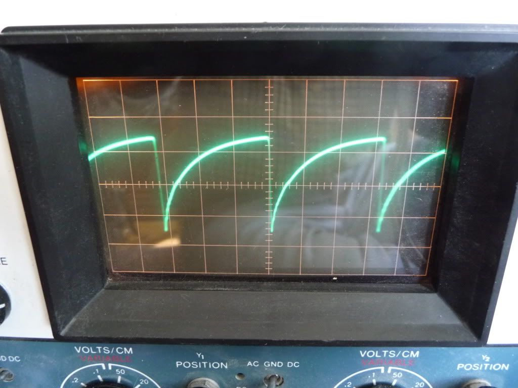 I don't know whether the RCA service manual misidentified the test point or if there's another problem. As time went on, I was having more and more trouble keeping horizontal lock. I also found that the horizontal hold control (which is actually the horizontal oscillator frequency control) had to be maxed out in one direction to achieve lock. I tried readjusting the sine wave coil, but it again seemed to have no effect. Eventually, I was unable to get horizontal lock at all. I powered the set down for a while, and when I powered it up again, I got no raster and the HOT started to red plate. I knew that I still had a bunch of maroon drop caps left which I thought might be the problem, so I pulled the chassis and changed out about 10 more, including those on the video amp/AGC board. When I powered up again, nothing had improved, the HOT red plated and no raster. I'm assuming that I must have lost horizontal drive, or that the horizontal frequency is way out of whack. I tried subbing tubes, and when I put in a NOS 6AU4 damper (even the the old one tests good) the HOT no longer red plated, but I still had no HV or raster (I also tried subbing a NOS 6DQ5). I'm not sure what that means. I inspected the fly, and I don't believe that it's the problem. The only caps left on the horizontal board are two mica caps which I didn't have replacements for. I am still pretty much a novice at this stuff and I'm not sure what to do next. I'm afraid of screwing something up. Incidentally, I never let it red plate for more than a few seconds. I'd like to be able to power up just the chassis on the bench, but I assume that that would not work without the deflection and convergence yokes attached. I may see if I can power up the chassis with everything connected but the chassis propped up behind the cabinet. That would allow me to finally measure the HOT cathode current. Anyone know if that's possible? I'm feeling a bit frustrated at the moment. Thanks for any advice, Clark
|
|
#65
01-24-2012, 10:00 AM
|
|||
|
|||
|
did you check under the IF cover for any bumble bee caps? there is a .01 in there that couples the noise invert to the sync sep, seems like it could cause issues with sync.
I am going thru a CTC-9 now. What I do for what its worth is lift one leg of a cap, and use an old school cap tester. If the cap test bad, then I replace it, but before doing that I take the new cap and put it back on the cap tester. Most of the time the old caps leak but you can get some indication of the value on the cap tester. By leaving all the settings alone, and trying the replacement cap on the tester, you can do two things, verify the value of the replacement and verify the replacement it good. This step avoids 10x order of magnitude errors and finds the bad new caps. I have had a few of those yellow caps shorted when brand new.
|
| Audiokarma |
|
#66
01-24-2012, 10:09 AM
|
||||
|
||||
|
Hi Dave,
Thanks for the feedback. I'm pretty sure that I installed all the correct cap values, but I'll double check. The troubles I'm having now started after I recapped the horizontal and vertical boards and everything was cool for a while. But I didn't check the new caps before installing them, so I could have installed a bad one. They do seem kind of cheaply made. I also have not checked the caps underneath the IF shield, so I will definitely do that. -Clark
|
|
#68
01-24-2012, 10:39 AM
|
||||
|
||||
|
Quote:
 I'm surprised that it worked as well as it did. That probably explains the horizontal jaggies I was getting. I'll change it out and see what happens. I'm surprised that it worked as well as it did. That probably explains the horizontal jaggies I was getting. I'll change it out and see what happens.I hope to have some time this weekend to get back at it. Thanks again, Clark
|
|
#70
01-24-2012, 12:11 PM
|
|||
|
|||
|
Quote:
|
| Audiokarma |
|
#71
01-24-2012, 01:20 PM
|
||||
|
||||
|
One nice thing about the "new" way is that bumblebee caps are marked the same way only instead of digits they have resistor color coded stripes.
__________________
Tom C. Zenith: The quality stays in EVEN after the name falls off! What I want. --> http://www.videokarma.org/showpost.p...62&postcount=4
|
|
#72
01-24-2012, 01:33 PM
|
||||
|
||||
|
Quote:
Phil Nelson
|
|
#73
01-24-2012, 02:03 PM
|
|||
|
|||
|
My cap tester is one of my must used pieces of equipment.
I just replaced a couple caps in the 9, the .01 that couples the horz osc to the horz out and a .056 on the vert. One was a orange drop, very leaky, the other was a maroon, not as bad but still leaked well below rated voltage. Others tested just fine.
|
|
#74
01-26-2012, 08:37 PM
|
||||
|
||||
|
Quote:
__________________
Evolution... 
|
|
#75
01-29-2012, 02:57 PM
|
||||
|
||||
|
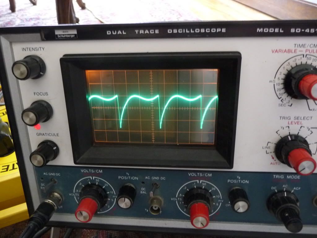
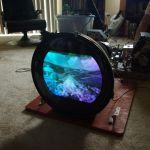
Success! I replaced the cap on the horizontal board with the correct value, but the HOT was still red plating. I pulled the 6DQ5 and found that I had a dead horizontal oscillator. After futzing with it for a while, I discovered that the NOS 6CG7 that I had installed was the culprit. It still tests fine but was no longer working in the circuit. I put the old, weak tube in place and the oscillator fired right up. This time, I was able to easily adjust the sine wave coil for the proper waveform:
 Now the horizontal lock is nice and stable with the control in the middle of its range. the horizontal jaggies seem to have disappeared. There are now just a few "maroon drops" remaining and things are looking pretty good: 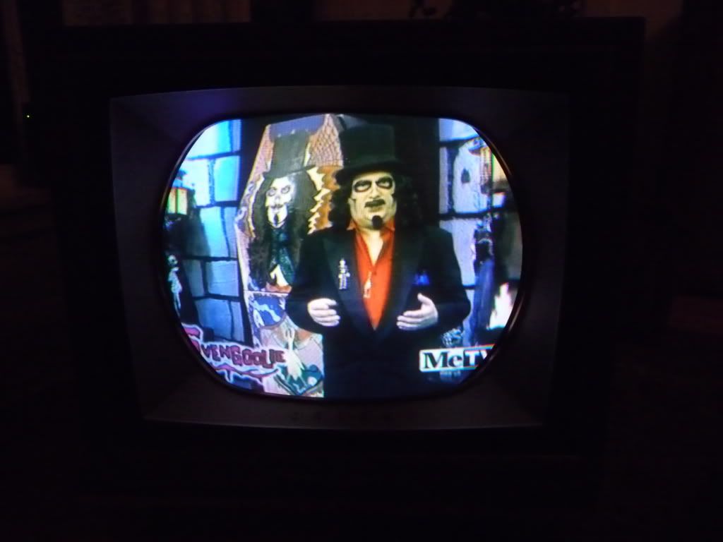 I still need to go through the entire purity/convergence set up. I discovered that none of the hairpin purity magnets are missing after all. A couple had been moved to normally unoccupied positions. I think they need to be remagnatized, too. Thanks again for the help! -Clark
|
| Audiokarma |
 |
|
|


 Linear Mode

