
|
|
|
#46
 01-04-2012, 08:42 AM
|
||||
|
||||
|
Quote:

__________________


|
|
#47
01-05-2012, 08:38 AM
|
|||
|
|||
|
Actually, the 4 was one of the easier sets I've worked on. Most things remained about the same after the CTC-4 and 5, which were each special in their own ways. The 4 detected color on different axes than any other set before or after: R-Y and G-Y vice the typical R-Y and B-Y that came later, or I/Q that came before, along with having high level demod. The 5 had a funky demodulator circuit using 12AT7's. The CTC-7 and everything thereafter looks the same on paper, subtle changes only. Most of it is different tube types, but later ones also shed an IF stage or 2 due to getting tubes with higher gain.[/QUOTE]
Nick.... The CTC5 had two different chassis that year. The better model had a color circuit that was simular to the later chassis.
|
|
#48
01-05-2012, 01:18 PM
|
||||
|
||||
|
The "super"=cheaper, the "deluxe"=better. I have a "super"
__________________
"It's a mad mad mad mad world" !! http://www.youtube.com/user/mwstaton64?feature=mhee
|
|
#49
01-05-2012, 07:59 PM
|
||||
|
||||
|
Quote:

__________________
Evolution... 
|
|
#50
01-08-2012, 04:07 PM
|
||||
|
||||
|
Quote:
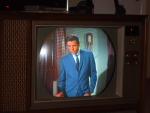
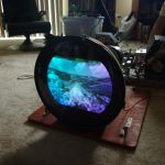
Nick, what does "high level demodulator" mean? As of Wednesday I got the cabinet up stairs and dismantled the CRT mask/safety glass/trim assembly for cleaning. On Thursday I cleaned the disintegrated rubber gasket from the Glass and mask. I used Goof Off to get the rubber off the glass, and started to use it on the mask. I then realized that it would be too harsh on the paint of the mask, and switched to rubbing alcohol, which is also not particularly good for the paint, but less harsh and yet still efficient at dissolving the rubber goo. 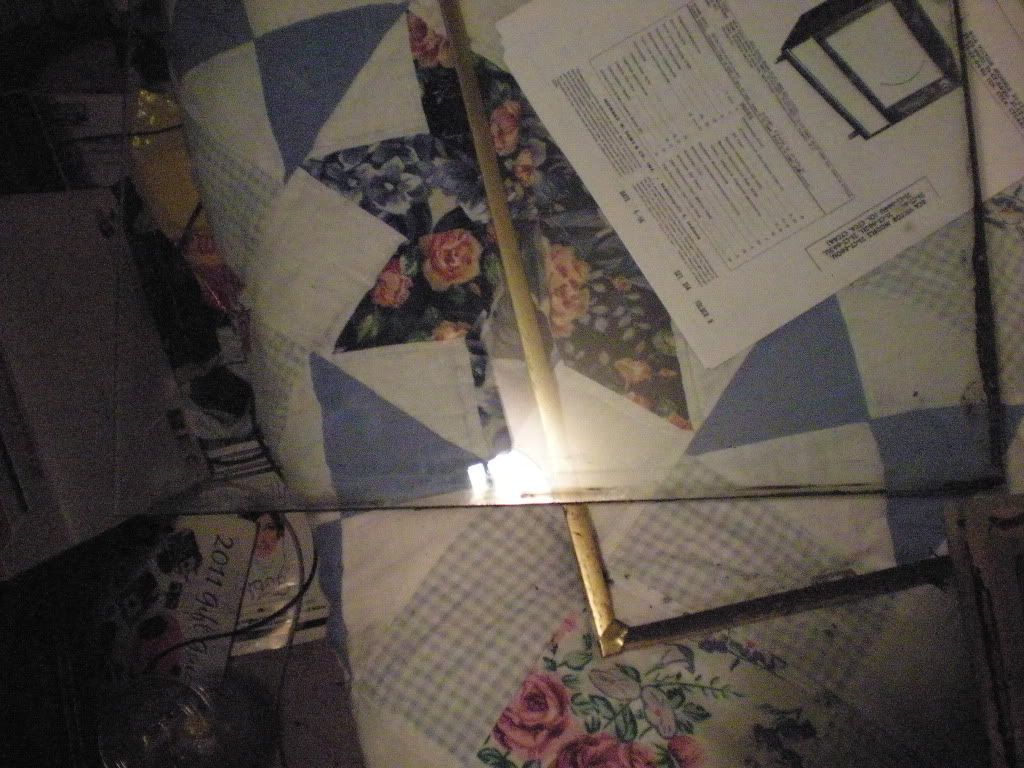 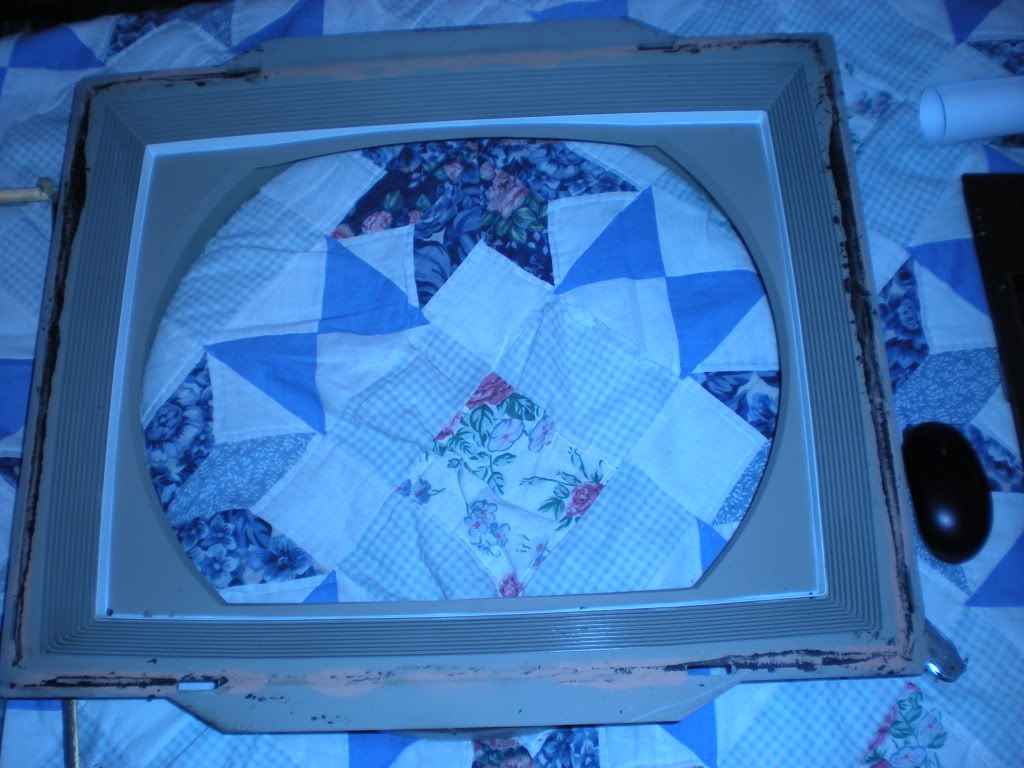 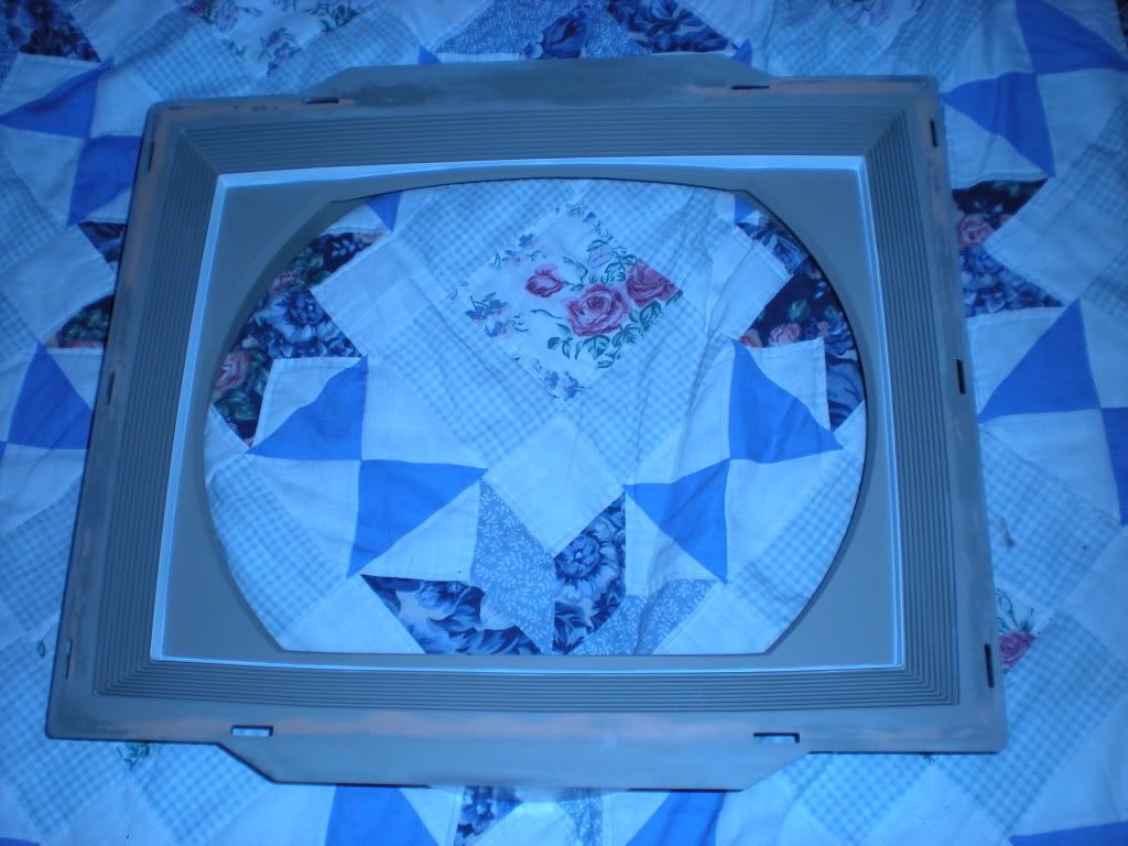 On Friday I started to polish the the the brass trim. It was not going fast at all on the lightly tarnished piece I started on. After that piece was good on Saturday, I grabbed the worst corroded piece I had and started experimenting with technique, and found that vigorously scrubbing the polish on with a tooth brush was VERY effective. Sadly even though it looks good from a distance it is clear up close that these pieces are brass plated copper, and that all pieces have spots of varying size where the plating was corroded through over the years. 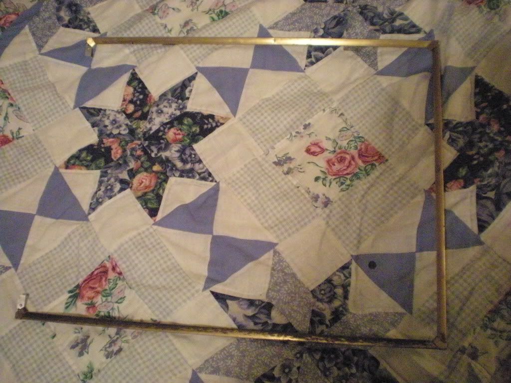 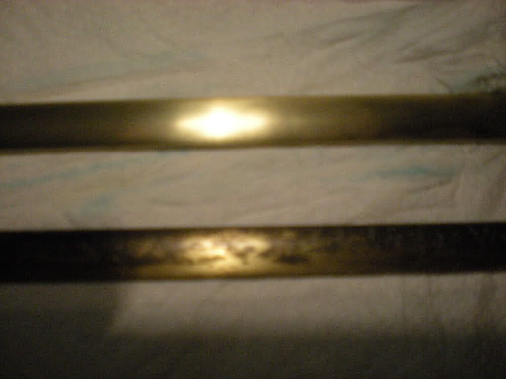 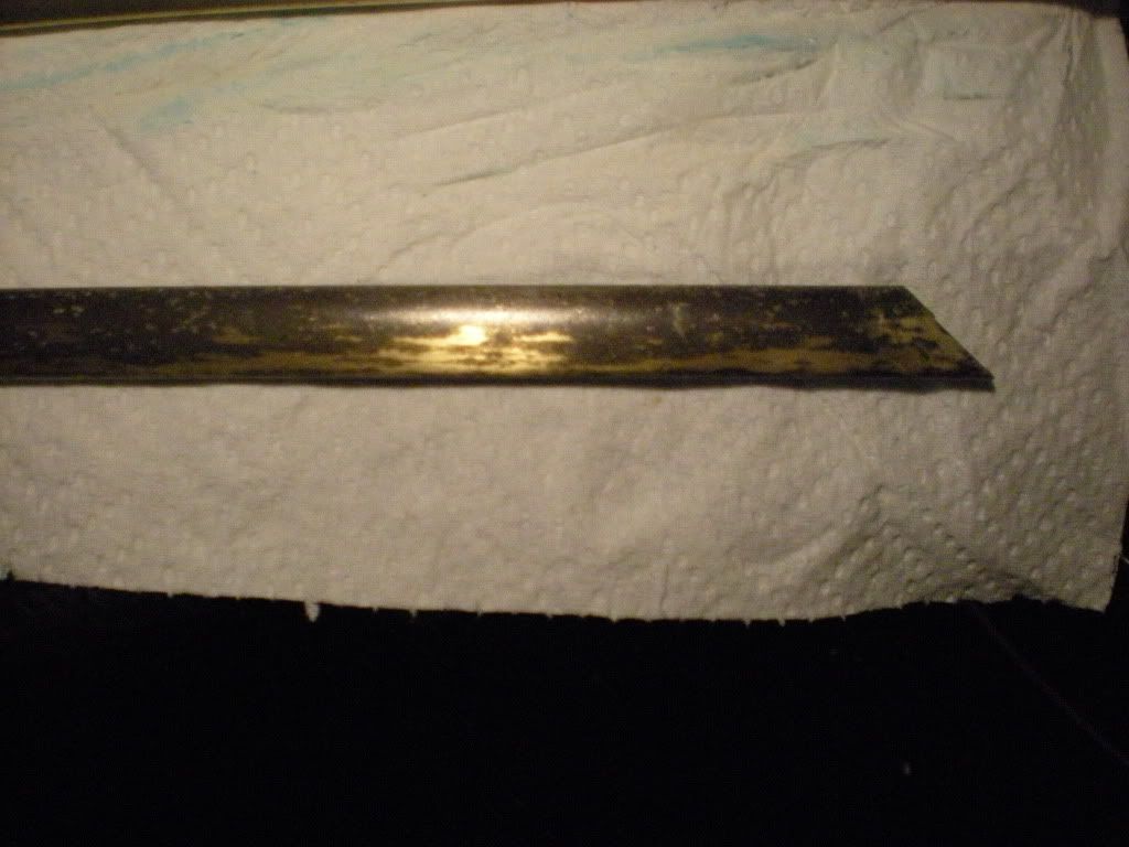 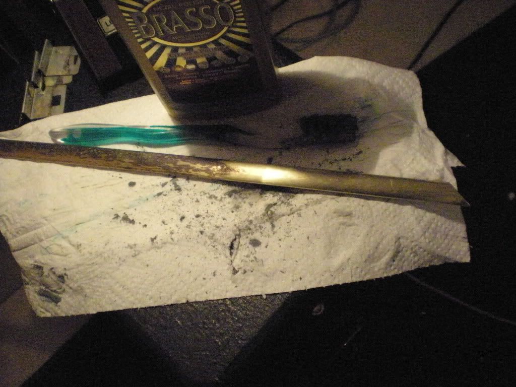 Nick I found out why those corner pieces were loose....Their retainer clips are busted. On the left is a good one the two others are the bad ones. 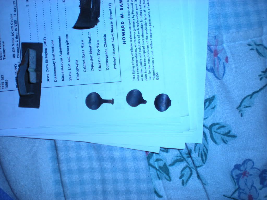 I mounted the corner pieces with the bad retainers at the top, and reinstalled everything in this picture. 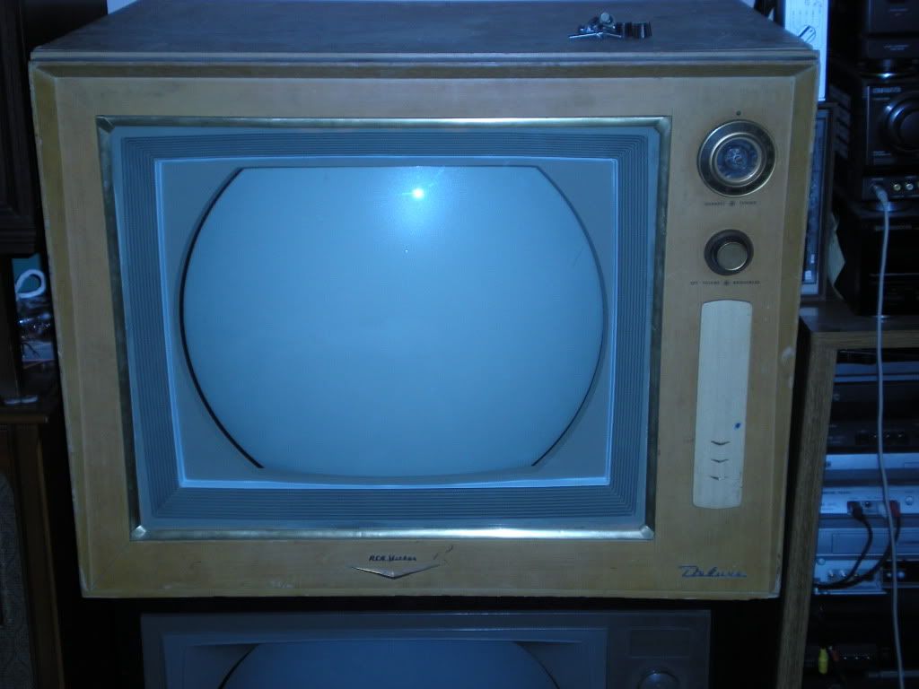 I did a quick green purity (at the time the red would not work) and neglected to take a picture. I was confounded by the red not working for some time, but then found that there was a lead touching the screen wire terminal that was shorting the screen to ground  It looked much better after that. It looked much better after that.The color circuits work, and I did some minor convergence tweaks to improve the picture. I still need to spray deoxit into some of the convergence pots as they can get squirly and mess with the deflection circuits. Still tons of adjustments to do which I'm going to need to fabricate a yoke extension cable to preform, and then hope that either the convergence will reach where I need it or that the set will not mind having the convergence yoke unplugged. 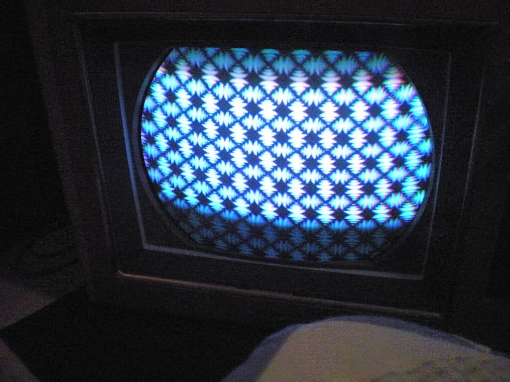 And what Nick has been wanting to see.....Color bars. 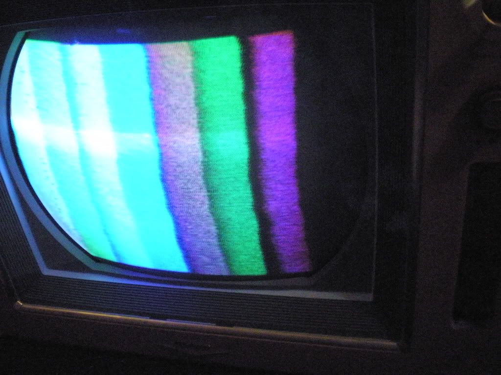 My camera made the left side look worse than it is, but it is clear that the demods need adjusting. There is a nasty imtermitant that kills the signal at the second IF tube. I'm begining to wonder if the socket is bad..... I actually lifted that set (minus the top lid) on to the black roundy my self. If it was not for the sore mussels I'd have been pretty proud of doing that.  
__________________
Tom C. Zenith: The quality stays in EVEN after the name falls off! What I want. --> http://www.videokarma.org/showpost.p...62&postcount=4
|
| Audiokarma |
|
#51
01-08-2012, 07:10 PM
|
||||
|
||||
|
Hi level demods go directly to CRT grids with no further amplifiers.
|
|
#52
01-08-2012, 08:21 PM
|
||||
|
||||
|
Correct. If you look at most other schematics, you'll notice that each color has an output tube. On the 4, the demods go directly to the CRT without passing go or collecting $200. Thus it's high level, where the circuits requiring amplification are considered low level.
__________________
Evolution...
|
|
#53
01-09-2012, 06:07 PM
|
||||
|
||||
|
Tom,
The trim is SOLID brass. It is not plated copper. Brass is acutally COPPER, that is alloyed with zinc. The copper pits or spots you see in the brass finish are areas where the zinc has likely been depleatd from years of chemical corrosion. When that happens the base metal COPPER is what is left and it looks like it was brass plated copper. I can asure you that the trim is solid brass and you can steel wool and scotch brite until you are blue in the face and you will never wear through the plating because it is not plated, it is solid brass. For an easy way to polish solid brass trim follow this link to my web site. http://antiquetvguy.com/Web%20Pages/...finishing.html Good Luck, Bob
__________________
Vacuum tubes are used in Wisconsin to help heat your house. New Web Site under developement ME http://AntiqueTvGuy.com
|
|
#54
01-09-2012, 07:46 PM
|
||||
|
||||
|
That is pretty cool Bob! I'll have to try that sometime.
I'm trying to preform the horizontal adjustments and have hit two walls the worst of which is that the linearity coil slug is BADLY frozen (I sprayed some deoxit gold in there and nothing) I'm afraid to proceed because I may end up breaking it. Please help! Secondly in the HV adjustment procedure it says to adjust the HV control for 25KV, and the most I can get before bottoming out the control is 20KV. Is this something that will shake out if I iterate the procedure a few times? Putting a meter in place of the HV fuse I'm getting around (ie a little over) 175mA of current.
__________________
Tom C. Zenith: The quality stays in EVEN after the name falls off! What I want. --> http://www.videokarma.org/showpost.p...62&postcount=4
|
|
#55
01-09-2012, 08:18 PM
|
||||
|
||||
|
Sounds like the output tube isn't being driven hard enough, have you checked the oscillator for correct performance? My CTC-4 will make 25kv no problem, same with the 21-CT-55. They have very stout HV supplies, so if you can't get more than 20 I'd look for issues in the drive or make sure it's not being dragged down somehow. Check that the output has the correct negative grid bias, and make sure the waveform going into it is of the correct amplitude and shape. If that's not it, juggle HV rectifiers till it comes up. I went through 3 of them before mine was stiff enough, just because they are new doesn't mean a whole lot. I've found that color sets in particular are very picky about what rectifier they have in them.
__________________
Evolution...
|
| Audiokarma |
|
#56
01-09-2012, 08:49 PM
|
||||
|
||||
|
Before the first power up I adjusted for the EXACT HOT grid drive voltage called for in sams as a safety precaution. The wave form looked decent, but I did not compare it to the sams at that time.
I just preformed the synchro-guide horizontal adjustment for equal peaks so the drive may have fluctuated, but I seem to recall that the HV was hovering at around 20KV before that so it may not have affected the drive level. The sam's High Voltage Adjustment procedure is to,with contrast and brightness down, adjust the HV pot for 25KV connect a 0-500mA meeter (I only have a 0-250 unit on hand) across the HV fuse terminals, and adjust the linearity slug for minimum current. Then reset the cont. and bright controls for a raster, and adjust the drive pot until drive bars appear then back off until they are gone. I was planning to iterate the process until things improved, but I'm hung up at the linearity adjustment because the lin. coil is stuck almost like gremlins have been dumping excess super glue that they have been using elsewhere into the lin coil. Anyone know how to unstick linearity coil slugs? Even if I skip linearity and go to drive the linearity adjustment will be done in the next step or two and hang me up again then.
__________________
Tom C. Zenith: The quality stays in EVEN after the name falls off! What I want. --> http://www.videokarma.org/showpost.p...62&postcount=4
|
|
#58
01-10-2012, 12:26 AM
|
||||
|
||||
|
Well this sucks!! The damn flat head screw head on the copper adjuster rod for the linearity coil snapped off, but I finally got it loose using a combination of Goof Off poured in the track for the ferrite core and heating the coil by connecting it to 2 flashlight cells thus heating it.
I think I need a new core/copper adjuster rod assembly. Here is what it looks like.. 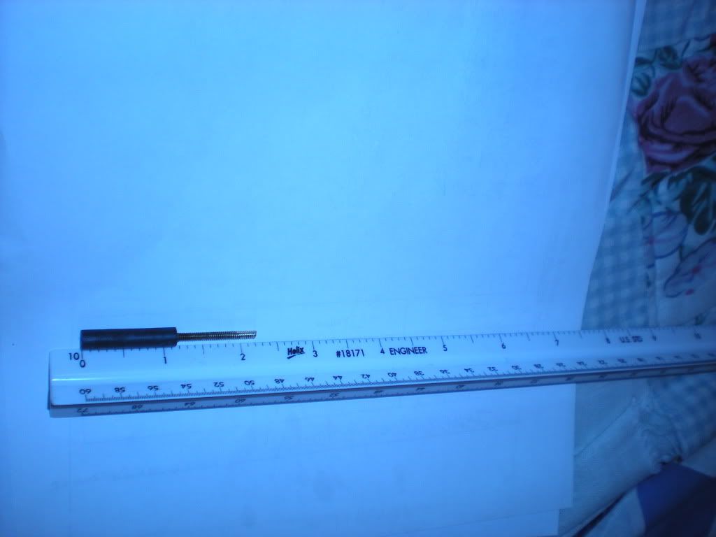 I'll try to see tomorrow if my RCA 9-T-246 has a similar core in one of it's coils that I can scrounge as a replacement for the original core with the destroyed adjuster threading. Been a lousy day between the rotten stomach bug that ruined my sleep Sunday night as well as making my folks tell me to skip school on Monday, and damaging this part. Ugh. Edit: all this happened before your post Nick.
__________________
Tom C. Zenith: The quality stays in EVEN after the name falls off! What I want. --> http://www.videokarma.org/showpost.p...62&postcount=4 Last edited by Electronic M; 01-10-2012 at 12:35 AM. Reason: add something
|
|
#59
01-10-2012, 11:41 AM
|
||||
|
||||
|
Same thing happened to my CT55, I just turn it with needle nose pliers. It should be possible to file a new slot into it, just be careful. Also, I always wanted to try brazing a knurled knob onto one of those.
__________________
Evolution...
|
|
#60
01-10-2012, 08:58 PM
|
||||
|
||||
|
Thanks for the advise Nick!
My file is a tad large, but if I can get the slug to rotate freely enough I ought to be able to get a screw driver to work with it after filing. I can't comment on the 21-CT-55 layout, but it would be kinda awkward to adjust the linearity control on the CTC-4 with pliers considering they wedged it between the damper and the HV cage. Not what I'd call a particularly good good place for it, but at least it is not as buried as the same adjustment in the CTC-16 (I tend to wear rubber gloves when doing live chassis horizontal adjustments on my 16's as the controls tend to be cramped, and uncomfortably close to dangerous voltages and searingly hot output tubes I'll try some other HV rect. tubes, but doubt they will fare better than what is in there. The tube in there is perhaps the first 3v filament HV rectifier that I've seen that will peg the needle on my tube tester, although I've heard the mantra that the best tester of TV sweep tubes is a TV set.
__________________
Tom C. Zenith: The quality stays in EVEN after the name falls off! What I want. --> http://www.videokarma.org/showpost.p...62&postcount=4
|
| Audiokarma |
 |
|
|


 Linear Mode

