
 |
|
#16
|
|||
|
|||
|
Here some more pics. I cleaned the chassis with some mild dish washing detergent. It wasn't real dirty and it cleaned up pretty well.
I checked the tubes and some are weak and some are very weak! I then got to work on making and ID on every capacitor and resistor and comparing it with the schematic and parts list. There were some discrepancies but nothing real major. I use a small block of masking tape and mark each component. While doing this I check the schematic and parts list. I then make the document changes in red ink. I also drew out the 2 tube configuration for the listed 6T8 tube. Besides using 2 tubes, there were a few resistors and capacitors in the chassis that weren't in the schematic. I'll update my parts lists accordingly so I get my order right. I'll draw up the new configuration and I'll post it side-by-side with the schematics so we can see what the changes were. 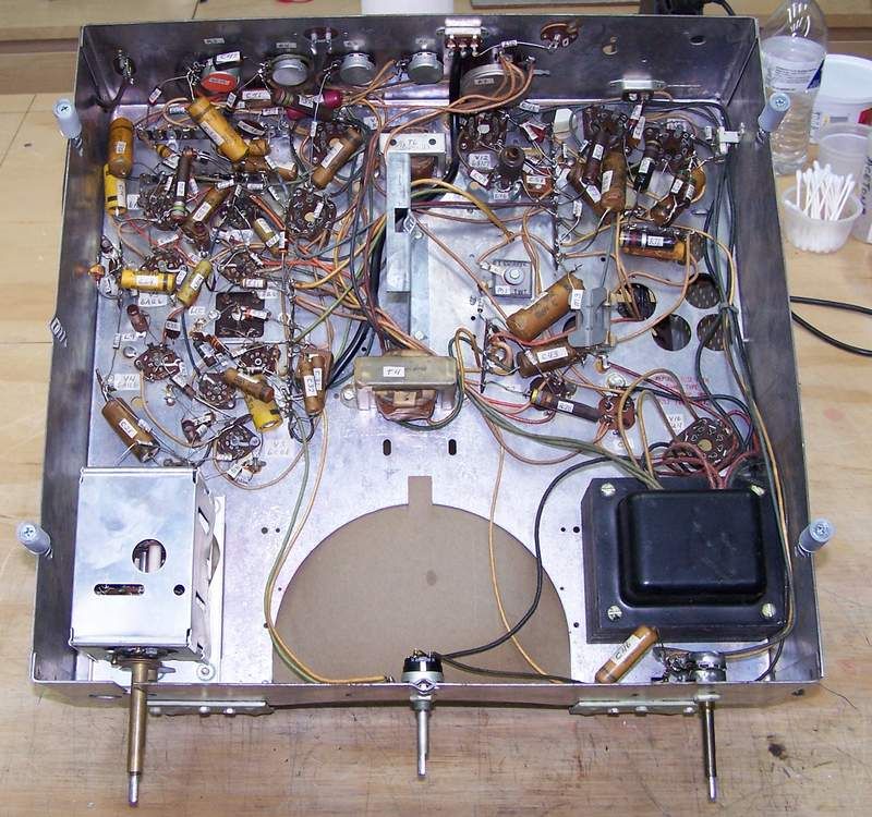 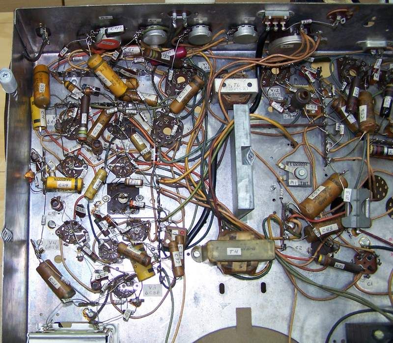 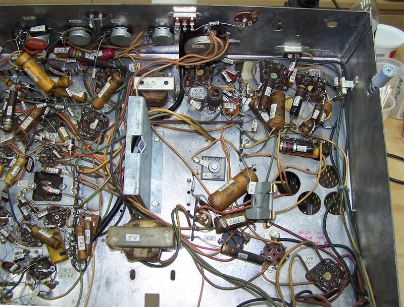
Last edited by Crist Rigott; 12-04-2016 at 12:28 AM. |
|
#17
|
|||
|
|||
|
Quote:
 It seems, at the time, just about every set manufacturer used at least three stages of IF. Bendix also designed the 12" set, using the 6BG6 reflex circuit horizontal osc and output and the damper less hv sweep circuit. Muntz copied that design, not the other way around. 
|
|
#18
|
|||
|
|||
|
In order to get fine detail resolution in the pic, the IFs have to be stagger tuned. And stagger-tuning reduces overall gain. Add another IF stage for more gain, and you can stagger-tune for a wider IF bandpass, allowing finer detail resolution. So more IF stages equals better fine detail in the pic.
(Then into the 1960s, high gain IF tubes were developed (e.g., 6EH7, 6EJ7) which allowed good bandpass with just two IF stages.) |
|
#19
|
|||
|
|||
|
That set is a Bendix set. The 2 tube sound mod was due to the FCC allowing TV stations to reduce their Aural power to a percentage of the Visual power. When that happened, some sets, including your Bendix, with only 2 IF stages, had low sound, if they were located in B or worse coverage area. Some companies marketed a 2 tube "kit" to boost the sound. broadcaster
|
|
#20
|
|||
|
|||
|
Was that with the advent of intercarrier sound?
|
| Audiokarma |
|
#21
|
|||
|
|||
|
Well I traced out the audio circuit and drew up the changes. I'll attach a pdf of the "before" and "after" the audio mod was done at the factory.
Some comments are in order. 1) SAMS made a mistake and reversed the polarity of Cap C3. This was confirmed by looking at the picture of the resistor location in the actual SAMS folder. 2) I eliminated the extra switching shown on the schematic showing switching for a combo unit. Mine is a table top model. 3) With the audio mod there were 3 components added not counting the tube. R79, R80, and C64. I gave them these designations to continue with the SAMS. 4) R37 was changed from 82K to 1.5MEG, R35 from 10MEG to 5.6MEG, R32 from 12K to 13K. As a general observation, I noticed that about 10 to 12 resistors are different values from the schematics. Consistent was the change from 47K resistors to 39K and 12K to 11K and 13K. Could have been caused by parts shortages? You guys that are more knowledgeable than myself, could you look over what I drew up and give me your comments? I drew up what I saw on how the chassis was wired. Thanks. |
|
#22
|
|||
|
|||
|
It's more likely there were parts shortages due to the war going on in Korea at the time. Big brother got first dibs on everything. All the best, Tom
|
|
#23
|
|||
|
|||
|
Quote:
There was several firms that didn't use 6T8's. Admiral, RCA, Motorola to name a few. |
|
#24
|
|||
|
|||
|
Quote:
I wonder what the reason was? 
|
|
#25
|
|||
|
|||
|
I wondered about that little selenium too, thinkin' maybe it was a neg.bias supply. But couldn't spy it in the schematic.

|
| Audiokarma |
|
#26
|
|||
|
|||
|
That's a centering circuit, you found it used alot in newer sets most noteably color sets. The late Jack Darr service editor for Radio-Electronics gave a good description on it. Still trying to find the artical. All the best, Tom
|
|
#27
|
||||
|
||||
|
CT-100 (and TRK-12) have FIVE IF stages!
Yes, more gives more gain.. BUT ... it also allows a more sharply tailored bandpass curve with a very sharp 4.2 MHz cutoff. Doing the sharp bandpass edges cuts overall gain. |
|
#28
|
|||
|
|||
|
The last day or so was spent taking inventory of what parts are needed and making a list and where to get them from. Some I had "in stock" while others will be ordered from Just Radios and Digikey. I've decided to bump up the 1/2W to 1W, the 1W to 2W and the 2W to 3W. Some of the 2W resistors seemed a bit discolored and heat stressed so those 3 will be replaced with 5W (R70, R71, R73). There was one resistor clearly bad. It had split open due to excessive heat. It is R76 a 470 ohm 2W resistor. This will be replaced with a 470 ohm 10W resistor the local parts house had in stock. It will still fit nicely in the chassis.
I'm using the taller, slender Nichicon 105c E-Caps so they'll fit into the cans. There are 2 cans with 3 each caps in them 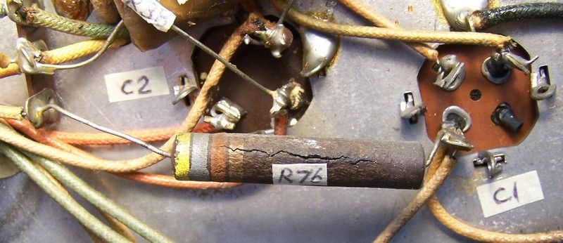 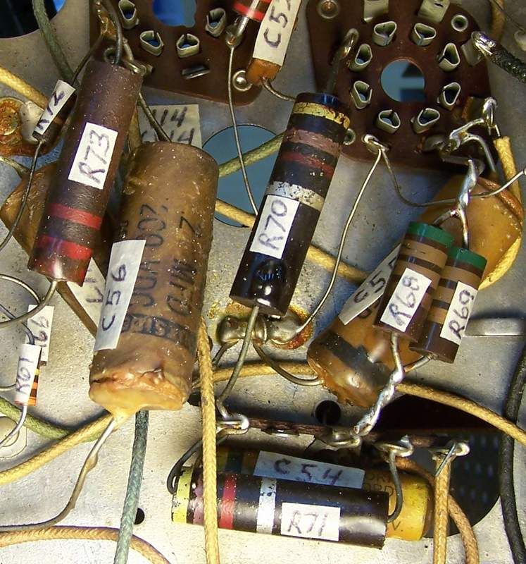
Last edited by Crist Rigott; 12-04-2016 at 12:30 AM. |
|
#29
|
|||
|
|||
|
While I wait for the parts to arrive I'd like to clean up the HV cage. Never having done a TV before with a flyback I could use some guidance. I want to clean this up and of course replace the 2 680K 2w resistors with 2 680K 3w resistors and the .00047 10Kv cap with a .00047 15Kv cap from Just Radios.
It liiks like I could remove the cage portion by unscrewing it from the chassis, removing the flyback mounting screws, and the 1 screw holding the phenolic standoff. Once that is removed I can access the the electrical parts. Here's where I could use some help. I'm thinking of removing the wires from the flyback phenolic board and releasing the clips on the 1B3GT tube socket to completely remove the "guts" so I can work on them on the bench. My other option is to unsolder the flyback wires from underneath the chassis instead of from the flyback board. I've included close up pictures of what I have to work with. Also there is a very small separation of the flyback tape on the top of the flyback. Should I look at repairing this or just leave it alone? What should I use to clean the whole thing off with? I usually use some rubbing alcohol, Q-tips, etc. While I have it out, is there anything else that needs to be done to it? Thanks. 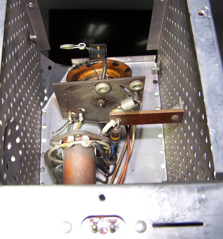 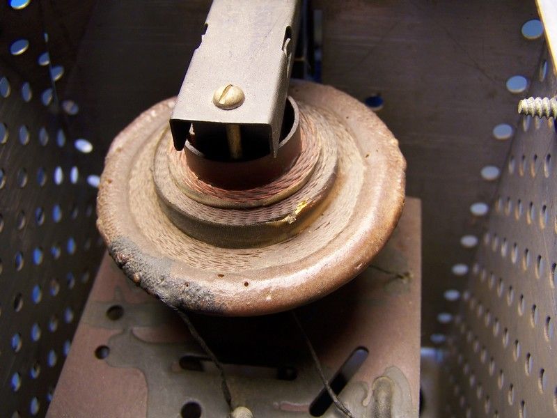 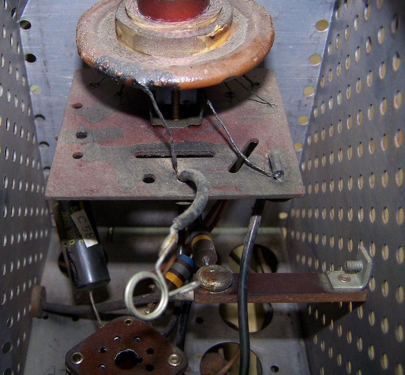
Last edited by Crist Rigott; 12-04-2016 at 12:32 AM. |
|
#30
|
|||
|
|||
|
Avoid unnecessarily doing anything around a flyback. Those thin wires are very prone to damage.
. |
| Audiokarma |
 |
|
|