Videokarma.org

Go Back   Videokarma.org TV - Video - Vintage Television & Radio Forums > Early B&W and Projection TV

We appreciate your help

in keeping this site going.
Reply
 
Thread Tools Display Modes
  #16  
Old 03-09-2017, 12:37 PM
Zenith26kc20's Avatar
Zenith26kc20 Zenith26kc20 is offline
VideoKarma Member
 
Join Date: Apr 2009
Location: New Orleans
Posts: 824
Have you checked the value of the vertical controls? I had a open vertical centering on a TS-18 that drove me nuts! It had sweep, just bizarre. I had another one with 1/2 the value on vertical centering control. I had to add resistors on each end. Once I did, it worked great.

Last edited by Zenith26kc20; 03-09-2017 at 12:38 PM. Reason: bad spelling! Sorry!
Reply With Quote
  #17  
Old 03-09-2017, 12:54 PM
timmy's Avatar
timmy timmy is offline
VideoKarma Member
 
Join Date: Jan 2011
Location: ferndale ny
Posts: 3,518
Quote:
Originally Posted by Zenith26kc20 View Post
Have you checked the value of the vertical controls? I had a open vertical centering on a TS-18 that drove me nuts! It had sweep, just bizarre. I had another one with 1/2 the value on vertical centering control. I had to add resistors on each end. Once I did, it worked great.
Both the vert hold and the size are good, ohms wise and the vert centering works correctly. This set is bizarre since I cannot find anything wrong.
Reply With Quote
  #18  
Old 03-09-2017, 01:45 PM
jr_tech's Avatar
jr_tech jr_tech is offline
VideoKarma Member
 
Join Date: Sep 2009
Posts: 4,510
Do you still have the mis-matched capacitors in the vertical output?
Are you absolutely positive the vertical circuits are wired correctly?

Do you have a spare vertical oscillator transformer?

jr
Reply With Quote
  #19  
Old 03-09-2017, 02:08 PM
timmy's Avatar
timmy timmy is offline
VideoKarma Member
 
Join Date: Jan 2011
Location: ferndale ny
Posts: 3,518
Quote:
Originally Posted by jr_tech View Post
Do you still have the mis-matched capacitors in the vertical output?
Are you absolutely positive the vertical circuits are wired correctly?

Do you have a spare vertical oscillator transformer?

jr
I still have the different caps in place but they both test what they should in NF 4.50NF and I went over the SAMs and more then double check everything. Which is the vert oscillator trans T? I may have one from another set. I don't think there is a vert oscillator trans in the ts18.
Reply With Quote
  #20  
Old 03-09-2017, 02:18 PM
jr_tech's Avatar
jr_tech jr_tech is offline
VideoKarma Member
 
Join Date: Sep 2009
Posts: 4,510
You are correct... no VOT in the set... sorry !

jr
Reply With Quote
Audiokarma
  #21  
Old 03-09-2017, 03:02 PM
bandersen's Avatar
bandersen bandersen is offline
RCA 741PCS
 
Join Date: Mar 2009
Location: Chicago, IL
Posts: 8,096
Is one of the caps in the vertical ceramic ? It's capacitance will change when high voltage is applied causing problems. That's why you should use film or a ceramic cap much larger than what is called for. Swap the two caps around and see if the problem changes.
__________________
Here are my Vintage Radio & TV YouTube Channel and Photo Gallery
Reply With Quote
  #22  
Old 03-09-2017, 03:20 PM
timmy's Avatar
timmy timmy is offline
VideoKarma Member
 
Join Date: Jan 2011
Location: ferndale ny
Posts: 3,518
Quote:
Originally Posted by bandersen View Post
Is one of the caps in the vertical ceramic ? It's capacitance will change when high voltage is applied causing problems. That's why you should use film or a ceramic cap much larger than what is called for. Swap the two caps around and see if the problem changes.
I thought about switching them around. I did put several red film caps in series and parallel to make .005 but that didn't do anything to help. I have the one white tubular on one side and 2 ceramic 2kv caps on the other side and are equal to the NF of the other but if the capacitance changes with hv then I guess it won't work.
Reply With Quote
  #23  
Old 03-09-2017, 04:15 PM
jr_tech's Avatar
jr_tech jr_tech is offline
VideoKarma Member
 
Join Date: Sep 2009
Posts: 4,510
2kV??? those caps should be at least 6kV!

jr
Reply With Quote
  #24  
Old 03-09-2017, 04:51 PM
timmy's Avatar
timmy timmy is offline
VideoKarma Member
 
Join Date: Jan 2011
Location: ferndale ny
Posts: 3,518
Quote:
Originally Posted by jr_tech View Post
2kV??? those caps should be at least 6kV!

jr
I know 6 kv but I'll post a pic of the screen the way it is and another pic with a .01 cap paralleled with the .004 . This is baffling since it has a bright screen and a decent pic with these caps, which is only one side of the verticle has the ceramic.
Reply With Quote
  #25  
Old 03-09-2017, 04:57 PM
timmy's Avatar
timmy timmy is offline
VideoKarma Member
 
Join Date: Jan 2011
Location: ferndale ny
Posts: 3,518
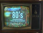
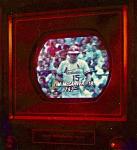
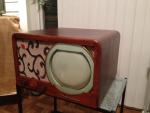
Ok here's the pics with the ca and without. And I tried another .004 I made up of film caps, 2 to match the pf. Ok the next post has the other pic.

Last edited by timmy; 04-24-2023 at 04:16 PM.
Reply With Quote
Audiokarma
  #26  
Old 03-09-2017, 04:59 PM
timmy's Avatar
timmy timmy is offline
VideoKarma Member
 
Join Date: Jan 2011
Location: ferndale ny
Posts: 3,518
And the other.

Last edited by timmy; 04-24-2023 at 04:16 PM.
Reply With Quote
  #27  
Old 03-09-2017, 05:42 PM
EdKozk2 EdKozk2 is offline
Tinker
 
Join Date: Mar 2014
Location: Elkhorn, WI
Posts: 542
Timmy,
Where did you ground the .004 cap, chassis or B- buss. It should be the B- buss.
Ed
Reply With Quote
  #28  
Old 03-09-2017, 05:50 PM
timmy's Avatar
timmy timmy is offline
VideoKarma Member
 
Join Date: Jan 2011
Location: ferndale ny
Posts: 3,518
Quote:
Originally Posted by EdKozk2 View Post
Timmy,
Where did you ground the .004 cap, chassis or B- buss. It should be the B- buss.
Ed
It's grounded to a factory tie strip that's tied to the 6sl7 that's where the .004 is grounded. Nothing was changed was all original where the cap was is where the new one went. The weird thing is upon turning it on for the first time it had a pic that rolled but the hold pot had to be maxed at one end to stop the roll then it went down hill fast to what I have now and it was good with those caps I have in there now . It's on b- not the steel chassis.
Reply With Quote
  #29  
Old 03-10-2017, 06:45 AM
timmy's Avatar
timmy timmy is offline
VideoKarma Member
 
Join Date: Jan 2011
Location: ferndale ny
Posts: 3,518
Ok there is no more ceramics in the verticle and still after putting together several 2 kv metalized caps in series to make 6kv and the proper NF for this application no change. Is it possible that the 2 ceramics in the horizontal could be causing this even though the horiz works perfect. The ceramics in the horiz are .002 10 kv. My mistake the caps in the horiz are .002 not .001 so I don't think that would make much difference.

Last edited by timmy; 04-24-2023 at 04:16 PM.
Reply With Quote
  #30  
Old 03-10-2017, 06:51 AM
compucat's Avatar
compucat compucat is offline
1949 Motorola 9VT1
 
Join Date: Apr 2005
Location: Suffolk, VA
Posts: 970
You need the correct 6kV tubular caps in the vertical circuit to have correct linearity. The mix and match does not work well here.
__________________
Just look at those channels whiz on by. - Fred Sanford
Reply With Quote
Audiokarma
Reply


Thread Tools
Display Modes

Posting Rules
You may not post new threads
You may not post replies
You may not post attachments
You may not edit your posts

BB code is On
Smilies are On
[IMG] code is On
HTML code is Off

Forum Jump


All times are GMT -5. The time now is 09:21 AM.


Powered by vBulletin® Version 3.8.4
Copyright ©2000 - 2024, Jelsoft Enterprises Ltd.
©Copyright 2012 VideoKarma.org, All rights reserved.