
|
|
|
#16
 01-13-2016, 02:36 PM
|
|||
|
|||
|
The most frequent causes of loss of luma are 1. Dirty Service Switch (but I don't believe CTC-5 has a Service Switch) and 2. Heater-cathode short in the CRT.
Try tapping gently on the CRT neck with something like a screwdriver handle. That'll usually show up a H-K short. Other things can cause loss of luma too, including open delay line. 
|
|
#17
01-13-2016, 02:38 PM
|
||||
|
||||
|
Looks like I had it in my first picture of the set without the color...
__________________
 Admiral C322C2 Regent (Restoring) RCA CTC-7 Pensbury (Restored) RCA CTC-5 Westcott (Restored) CRA CTC--4 Director 21 (Restoring)
|
|
#18
01-13-2016, 02:39 PM
|
||||
|
||||
|
I also suspect the chroma takeoff and 4.5 mc coil may have something to do with it. The crt checks fine with the H-K so I dont think it can be that.
__________________
Admiral C322C2 Regent (Restoring) RCA CTC-7 Pensbury (Restored) RCA CTC-5 Westcott (Restored) CRA CTC--4 Director 21 (Restoring)
|
|
#19
01-13-2016, 03:11 PM
|
||||
|
||||
|
If you have a test pattern generator with a strong variable level video output I'd use it the try injecting video to various points in the monochrome signal chain (use a cap in series with the video lead to prevent DC from damaging the unit unless you know the generator has one built in). Start at the monochrome video output (if injecting at the grid gives you video work towards the detector till you loose it otherwise work towards the CRT till you get video). If you have an audio/RF signal generator you may be able to use that in place of the video generator by finding a frequency that is a multiple of the vertical and or horizontal scan rate...I did that in a pinch once, and it worked well....So well that I ended up playing with different frequencies to see what kinds of patterns I could make.
 If you have an oscilloscope you can trace the video forward from the detector till you loose it. Best to use a vertical bar gray-scale test pattern for the scope method since it will give you a nice easily recognizable stair stepped pattern between the sync pulses.
__________________
Tom C. Zenith: The quality stays in EVEN after the name falls off! What I want. --> http://www.videokarma.org/showpost.p...62&postcount=4
|
|
#21
01-13-2016, 05:24 PM
|
|||
|
|||
|
In your screen shot it looks like the chroma level, color sync etc. are good. So turn the color control completely all the way down. Forget about color for now. It's a completely separate system from the luma (B&W video) chain. With the color off, the set should show a normal B&W picture.
The luma chain is what you need to work on. ----- On a related note, remember that in a tube type color set, luma goes into the CRT via the cathodes; color goes into the CRT via the (G1) grids.
|
|
#23
01-13-2016, 08:07 PM
|
||||
|
||||
|
Quote:
anywhere along the line, don't get stuck on some single part just cause you know it's name, troubleshoot it along the way.... Contrast control, tube, check tubes & tube voltages, lose parts, tube sockets, hit stuff and boards with a nude stick see if it's intermittent, etc. etc.... .
__________________
Yes you can call me "Squirrel boy"
|
|
#24
01-14-2016, 07:18 PM
|
||||
|
||||
|
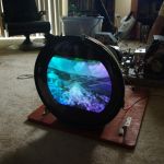
OK the 4.5mc coil was badly out of alignment so I readjusted that with my scope. I think I now have a pretty good picture for a CTC-5 super. Aside from the purity issues it looks pretty good in person. I will do edge purity and a bit of convergence since the convergence already looks good. Then I will take a look at the HOT cathode current and adjust that if needed. Also going to add a fan to the HV cage to keep the fly cool. And then I may be already done with this restoration!
__________________
Admiral C322C2 Regent (Restoring) RCA CTC-7 Pensbury (Restored) RCA CTC-5 Westcott (Restored) CRA CTC--4 Director 21 (Restoring)
|
|
#26
01-17-2016, 12:48 PM
|
||||
|
||||
|
I did some reading up on the A version of the 21axp22. The red dag coating was used to prevent internal arcing in the neck of the tube. Does this imply that the original 21ax had arcing issues inside the neck? We're the phosphors on the A version improved over the original?
__________________
Admiral C322C2 Regent (Restoring) RCA CTC-7 Pensbury (Restored) RCA CTC-5 Westcott (Restored) CRA CTC--4 Director 21 (Restoring)
|
|
#27
01-18-2016, 09:42 AM
|
||||
|
||||
|
There are at least 3 flavors of 21AXP22 that I'm aware of:
The earliest ones had the same phosphors as a 15GP22 giving a greenish look to the screen and had normal grey dag on the inside, the chassis they were used with always had series anode resistance to protect the flyback in case of an arc in the CRT. Part number would be 21AXP22. Next is the same tube, just with improved brightness from different phosphors. This one was used in most of the CTC-4's you see out there unless a replacement was installed, and it's easy to tell because the screen appears white instead of greenish. Part number is still 21AXP22, still all grey dag. Last version to come out before the glass tubes was the 21AXP22A. This is the one with a white screen and red resistive dag on the inside, which eliminated the need for series anode resistance for arc protection from the previous model. All CTC-5's used this tube and it's compatible with earlier chassis. The same is NOT true of putting a 21AXP22 (non-A) into a set having a CTC-5 chassis, which has no built in series anode resistance. While it's true it will 'work', the caution there is that without any series anode resistance you run the risk of shorting all HV anode current to ground in the event of a CRT failure. The whole point of series anode resistance is the protect the chassis, without it you blow up more parts when the CRT goes. So if you have a CTC-5 and your CRT has all grey dag, either install some resistance in the anode lead or prepare to replace the flyback if the tube dies. The red dag doesn't prevent arcing, it merely saves other parts from death should an arc occur.
__________________
Evolution... 
|
|
#28
01-21-2016, 04:01 PM
|
||||
|
||||
|
Checked the delay line. There were two leads coming out of one end and just one lead coming out of the other end. One of the two leads read .1 ohms and the other lead read 830 ohms. The side reading 830 ohms sounds like it could be causing the complete absence of luma. What do you folks think?
__________________
Admiral C322C2 Regent (Restoring) RCA CTC-7 Pensbury (Restored) RCA CTC-5 Westcott (Restored) CRA CTC--4 Director 21 (Restoring)
|
|
#29
01-21-2016, 09:29 PM
|
||||
|
||||
|
Quote:
Regarding your delay line resistance readings, are you measuring in-circuit or out? And exactly where are you connecting the ohmmeter?
|
|
#30
01-22-2016, 05:42 AM
|
||||
|
||||
|
The service manual I am reading is the one from the ETF website. I am reading the early set manual. I dont see anything that specifically says CRT bias setup. And I tested the delay line in circuit. I was measuring everything from the end with only one lead on the delay line.
__________________
Admiral C322C2 Regent (Restoring) RCA CTC-7 Pensbury (Restored) RCA CTC-5 Westcott (Restored) CRA CTC--4 Director 21 (Restoring)
|
| Audiokarma |
 |
|
|


 Linear Mode

