
|
|
|
#31
 06-02-2013, 07:42 PM
|
||||
|
||||
|
Yeah, kvflyer and miniman, I am really amazed and thankful the old CRT still works. It tested good on the CR70, but until I saw the screen light and no blue neck glow, I was holding my breath.
I can't wait to see color too, but that's for another day, soon hopefully. Dave 
|
|
#32
06-03-2013, 07:05 AM
|
||||
|
||||
|
Great progress!
|
|
#33
06-03-2013, 12:07 PM
|
||||
|
||||
|
Keep up the good work!
__________________
Tom C. Zenith: The quality stays in EVEN after the name falls off! What I want. --> http://www.videokarma.org/showpost.p...62&postcount=4
|
|
#34
06-03-2013, 09:15 PM
|
||||
|
||||
|
After swapping tubes, disconnecting the oscillator components, testing them, finding them ok, testing the caps inside the reactance transformer, and finding them ok I examined the crystal socket and thought it looked a bit corroded. I cleaned its socket and tried the oscillator adjustment procedure again. This time the oscillator started
 . So I adjusted it to the 5Vpp, and ran out of time for tonight. So I guess I will not need the replacement crystals and oscillator output transformer I ordered today. But its nice to have spares. I ordered an audio output transformer that I think may work even if its not a listed replacement. Its from an amp that also uses a 6AQ5 for its output tube. . So I adjusted it to the 5Vpp, and ran out of time for tonight. So I guess I will not need the replacement crystals and oscillator output transformer I ordered today. But its nice to have spares. I ordered an audio output transformer that I think may work even if its not a listed replacement. Its from an amp that also uses a 6AQ5 for its output tube.
|
|
#35
06-16-2013, 08:54 AM
|
||||
|
||||
|
Before I did the color alignment I wanted to try to lower the flyback drive current as much as I could without messing up the width, linearity, or adding visible drive lines. I tried making the HOT drive DC voltage more negative by increasing the grid to ground resistance, but too much adds drive lines. I found the HOT screen voltage was high, so I changed the 10K screen resistor to 11K and ended up adding 2.2K to that and just barely have enough width with the width switch set to max. I only got it down to around 200 mA without getting visible problems. I also messed with the 7.5 ohm silicon diode dropping resistor. I ended up with a 4 ohm dropping resistor to get right at 400VDC with my AC input voltage. To make checking voltages and currents easier later, I added a terminal strip on the transformer side of the selenium rectifier tower with low ohm resistors in series with the supply voltage rails so I can check voltage and current on the four rails. I also added a terminal strip to the back of the HV cage with a jumper to insert a current meter in the HOT cathode and a 10 ohm resistor in series with the HV regulator cathode to measure its current. With the chassis back in the set I did another horizontal and vertical alignment and ended up with 25KV HV, 205-200 mA HOT current, full vertical and full horizontal deflection with decent linearity. With the color oscillator now running I can see that the color is not locked.
Last edited by Zenith6S321; 06-16-2013 at 09:54 AM.
|
| Audiokarma |
|
#36
06-16-2013, 09:21 AM
|
||||
|
||||
|
I bolted the chassis into the cabinet and tipped it on its side so that I could get at the underside of the chassis and see the picture. I started through the color AFC alignment procedure but I could not get a zero beat pattern with the reactance tube input grounded. I put my Heathkit frequency counter on the color oscillator and found it running at 3.581391 MHz, pic attached. After scoping a few points I found a bad connection on the reactance transformer supply input. I guess it had been cut at some time and poorly soldered back. This is probably the reason I could occasionally get the color to lock 30+ years ago. With that fixed and some fiddling with the fine tuning I got the color to lock, but I still could not get a zero beat pattern when adjusting the reactance transformer. I could reduce the number of out-of-sync color bars, but there was not enough range to reach zero beat. I put the frequency counter back on the color oscillator and found that when it locked the frequency counter read 3.579445 MHz, pic attached. With the reactance transformer adjusted for the minimum number of color bars, the counter read 3.579653 MHz. So the reactance transformer would let me adjust the frequency down, but not down far enough to reach zero beat. I had one old crystal and five NOS I just bought, so I tried them and got these frequencies:
RCA crystal dated 11/56 3.579653 Crystek #1 3.579651 Crystek #2 3.579644 Crystek #3 3.579625 Crystek #4 3.579647 Crystek #5 3.579632 COYSON dated 3/75 3.579614 I put the Crystek #5 crystal back in, since it was about the middle of the set of frequencies, and verified it read the same after putting it back in. Then I added a 1pF ceramic cap to across the crystal and saw it lower the frequency. I ended up with 3pF across the crystal to get a frequency lower than the locked frequency with the reactance transformer adjusted for its lowest frequency. Now I could adjust the frequency up to get a zero beat of the color bars with the reactance input grounded. I did the rest of the color AFC alignment and ended up with color that remained locked with acceptable fine tuning. Last edited by Zenith6S321; 06-16-2013 at 10:00 AM.
|
|
#37
06-16-2013, 09:30 AM
|
||||
|
||||
|
The matrix alignment had me confused at first when looking at the R-Y scope pattern from a color bar generator. I realized the RCA color bar generator color sequence is not the same as my Sencore VA62 color bar sequence. Here is a list of the correspondence:
Pulse after burst---RCA--------------------Sencore VA62 --------1-----------yellow-orange----------green-blue --------2-----------orange------------------cyan --------3-----------red----------------------blue-green --------4-----------blue-red----------------green --------5-----------magenta----------------yellow-orange --------6-----------blue---------------------orange --------7-----------green-blue--------------red --------8-----------cyan---------------------blue-red --------9-----------blue-green--------------magenta --------10----------green-------------------blue (Sorry for the -'s, I don't know how to set up columns) I was able to do the matrix alignment after translating from the RCA to the VA62 color sequence numbers, but it was confusing for me. Last edited by Zenith6S321; 06-16-2013 at 10:02 AM.
|
|
#38
06-16-2013, 09:52 AM
|
||||
|
||||
|
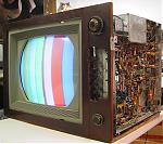
I dug out my old degaussing coil and ran it over the set. Here is a pic of the purity with all of the neutralizing magnets pulled out all the way. I took a shot at the convergence and found that even with restoration there is still a lot of interaction between the controls. My set has a CTC3 convergence chassis that matches the RCA service manual schematic, while my CTC2B chassis has what look to be running changes that more closely matches the Riders schematic. I may try modifying the CTC3 chassis to match the Riders to see if that improves convergence. Anyway, here are some pictures of the set with my attempt at the alignments. So far I have avoided doing anything inside the tuner, but the noise I see in the picture may motivate me to see if there are some drifted resistors as wiseguy found in his. The pictures on this set brings back memories of the color I saw 30+ yrs ago on this set and how amazed I was when I compared its colors to the 70's sets. I need to get a DVD of the Wizard of Oz and see how my sets compares to the CT100 pictures.

Last edited by Zenith6S321; 06-16-2013 at 10:10 AM.
|
|
#40
06-16-2013, 05:33 PM
|
||||
|
||||
|
Another 21CT55 Operational
Hey Dave, its looking good. Less than 18 weeks working the restoration so far is quite fast considering you went silicon rectifiers and big electrolitic cap stuffing. Of course you replaced the white RCA peaking coils and a number of small under-chassis yellow caps. Was this a less than mandatory complete re-cap or did it come this way? I really respect your logical, systematic approach to each problem you encountered and shared the process with the Members. I hope you get the Wizard of Oz for subjective evaluation of your 21CT55 picture quality and suggest also getting the " Digital Video Evaluation" DVD's test patterns for critical setup and objective PQ evaluation. Looking forward for your full-screen width, no room light, full computer monitor posted JPGs. I know what the 21CT55's are capable of so lotsa luck finishing this one off...........Tom
|
| Audiokarma |
|
#41
06-16-2013, 06:21 PM
|
||||
|
||||
|
Quote:
Dave
|
|
#42
06-16-2013, 06:37 PM
|
||||
|
||||
|
Quote:
After reading all the posts here, I wanted to try my hand at doing the restoration of my 21CT55 on my own, and ask for help here when I got stuck. So far so good. I also wanted to share the problems I ran into in case others find something similar. I will see if I can order the Wizard of Oz and will also look for "Digital Video Evaluation" DVD's test patterns. My camera is a cheap 7 Mpixel auto everything which probably will not be good enough to take good pictures in a dark room. How do you post high res pictures here?
|
|
#44
06-18-2013, 01:01 PM
|
||||
|
||||
|
Nice job getting it working.
__________________
Tom C. Zenith: The quality stays in EVEN after the name falls off! What I want. --> http://www.videokarma.org/showpost.p...62&postcount=4
|
|
#45
06-18-2013, 06:27 PM
|
||||||
|
||||||
|
Quote:
Quote:
Quote:
Quote:
Quote:
Quote:
Here's hoping you have good luck too! Hope you get better soon. I know its hard to be patient but these sets weigh a ton and you don't want to injure yourself or the set. Its probably best to take your time with the restoration and wait until you are back at 100% before moving that heavy chassis. Better yet, maybe you can get some help moving it. Dave
|
| Audiokarma |
 |
| Thread Tools | |
| Display Modes | |
|
|


 Linear Mode

