
|
|
|
#16
 08-17-2015, 10:49 PM
|
|||
|
|||
|
Quote:
UPDATE: The hum I was hearing wasn't from the filter capacitors being bad, it was from a loose wire on the cartridge on the turntable assembly and I know that's what the hum was from because when I turned the volume control it lowered the volume on the humming sound which indicates that it was because of the loose wire on the cartridge and not because of bad filter caps because if it was because of bad filter caps the humming noise wouldn't of been volume dependant and it would of stayed at a constant volume no matter what the volume control was adjusted to. So I'll just resolder the loose wire on the cartridge and it should take care of the hum and it should be good to go. One question though, if Cadmium is so bad for us, then why do they still use it in modern Ni-Cd rechargable batteries then? and why did they use Cadmium to plate radio chassises and parts if it was so bad for us? Last edited by Captainclock; 08-17-2015 at 11:03 PM. 
|
|
#17
08-17-2015, 11:08 PM
|
||||
|
||||
|
Ni-Cd batters are not that popular anymore....having been supplanted by NI-MH and LI-oh or LI-Po types--which have FAR More energy density and capacity for given ounce of cell weight. I also think that it is figured that one will NOT bust open an old -NI-CD battery and then grind the cadmium in the mixture to find dust and then stand there an BREATHE the dust...
As for chassis plating....I THINK it wa smore along the line of "didn't know better" back then....about the health risks of Cadmium dust and such. Just like asbestos.... I would say it is a lOT more hazardous to breathe cadmium over the short-term than asbestos though... I have watched an old film on production of the 1929-30 Philco radio chassis sets and cabinets. It is SCARY...how LITTLE regard to worker safety there was then. NO interlocks on the metal presses. NO ventillation over the area where wood was being glued...with a LOT of fumes coming up and NO respirators on the workers...etc...etc..
|
|
#18
08-17-2015, 11:45 PM
|
|||
|
|||
|
Quote:
|
|
#19
08-17-2015, 11:58 PM
|
||||
|
||||
|
I never have messed much with mine....I am guessing that cap mounted on the SIDE of the chassis is the one you are talking about. If you can cut the volume totally and do NOT get hum...then it is NOT coming from the power supply I beleive.
Try and ground the phono chassis to the amp chassis--make SURE the ground connection is good between them. This should cut down on hum. Also--make sure all connections to the pickup are clean and secure and have continuity through them too.
|
|
#20
08-18-2015, 12:18 AM
|
|||
|
|||
|
Quote:
Last edited by Captainclock; 08-18-2015 at 12:26 AM.
|
| Audiokarma |
|
#23
08-18-2015, 01:31 AM
|
|||
|
|||
|
Quote:
 There is a Schematic glued onto the inside of the cabinet but its hard to tell where the 220k Ohm resistor is supposed to go to.
|
|
#24
08-18-2015, 08:07 AM
|
|||
|
|||
|
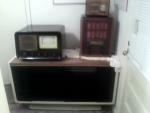
Ok I have some pictures of the record player being discussed in here, including pictures of the aforementioned resistor that seems to go nowhere in the amp chassis, and a picture of the schematic from the inside of the case.
Picture number 1 shows the 220k Ohm resistor in question and the fact that only one side of the resistor is attached to the circuit and the other side is currently detached from the circuit but from where in the circuit I'm not sure because the schematic (picture number 2) doesn't really show clearly where the reistor is supposed to go in the circuit clearly one side of the reistor was supposed to go to the positive terminal of the phono input jack, and the other side was clearly attached to the positive side of the tuner input jack (as the positive wire from the tuner input jack is still attached to the other side of the resistor) but as for where the detached side of the resistor was supposed to go in the circuit as a whole I'm not sure as its not marked very well on the schematic and might be why the amp and record player has a hum to it, but not sure, maybe someone on here can make better sense of the schematic than I can, because normally I don't have any issues with reading a schematic but this one is unusually hard follow for me some reason. Now for the last picture, I have a question about the supposed pilot lamp lens. For some reason or another the pilot lamp lense is a 5 inch long plastic rod that goes into the cabinet and rests up against a piece of wood that is flexible to the touch and when you push on the pilot lamp lens it goes into the cabinet and back out almost like a push button because of that piece of flexible wood it rests up against. My question is, why would they design the pilot lamp lens in that manner? It doesn't really make any sense and it definitely doesn't make any functional sense as it doesn't function as a push-button switch of any sort so why would you have a pilot lamp lense like that? The rest of the pictures are photos of the cabinet and the turntable.
|
|
#25
08-18-2015, 09:55 AM
|
|||
|
|||
|
The schematic shows the resistor connected accross the two jack hot terminals. Someone probably diidn't want it connected that way. Most units had a switch to select inputs.
The funky pilot lite lens, actually was an external reject push button, so you didn't have to open the lid to reject the record. If you assemble the unit, you'll see how it works. 
|
| Audiokarma |
|
#26
08-18-2015, 10:58 AM
|
||||
|
||||
|
Quote:
https://www.youtube.com/watch?v=bmqJce5xrfU jr
|
|
#27
08-18-2015, 11:53 AM
|
|||
|
|||
|
Quote:
 
|
|
#28
08-18-2015, 12:03 PM
|
|||
|
|||
|
Quote:
Would the lack of a seperate chassis ground wire on this unit be because this unit was meant to ground the turntable through the audio connector jack or power plug somehow, but maybe has a loose ground connection in the chassis itself for either the audio jack and or power jack depending on which plug the chassis ground was running through? Just wondering
|
|
#29
08-21-2015, 09:38 AM
|
|||
|
|||
|
Quote:
I wouldn't worry about the electrolytic, but I would change the .047 coupling caps to the 6V6 grids, pin 5.
|
|
#30
08-21-2015, 10:13 AM
|
|||
|
|||
|
Quote:
Thanks for the advice.
|
| Audiokarma |
 |
|
|


 Linear Mode

