
|
|
|
#16
 12-17-2017, 08:57 PM
|
||||
|
||||
|
My plan for the moment with the tuner is to replace the missing caps, align the tuner for the one channel I have a grid coil for (channel 2 or 5 I believe) and simply leave the set on that channel. Then, if that works, try to repair the remnants of the one coil form that is still present, giving two channels. If I can get that to work, then I'll try to make a wild ass guess as to final, completely missing, coil and tack in a replacement of a reasonable looking inductance.
If I can get the tuner to work on one channel at least I can restore the set. If all three coils were missing I would be up a creek. 
|
|
#17
12-17-2017, 10:07 PM
|
||||
|
||||
|
Quote:
__________________
Tom C. Zenith: The quality stays in EVEN after the name falls off! What I want. --> http://www.videokarma.org/showpost.p...62&postcount=4
|
|
#18
12-17-2017, 10:38 PM
|
||||
|
||||
|
Quote:
|
|
#19
12-18-2017, 12:08 PM
|
||||
|
||||
|
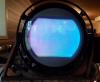
I may have found a CRT for this set. I really don't like the look of the getter flash, but I'm desperate for a 7EP4 to at least display the set with. Hopefully the owner will accept my offer for the jug (I think $150 is pretty fair) and I can stop the CRT hunt and focus on other missing parts.
  
Last edited by benman94; 12-18-2017 at 12:45 PM.
|
|
#20
12-18-2017, 03:30 PM
|
||||
|
||||
|
Unless you demand original look coils, with only three channels its easy.
Get some forms, new or used, even with wire on them, that mechanically fit and are for VHF. Install them and play with new windings and a grid dip meter until they are right. Stray inductances are so big that calculations are useless. I wish I had had a dip meter when I was working on my hacked TRK-12 RF area that had been hacked apparently TWICE by the RCA engineers themselves during the pre and post-WWII channel moves. I did use the dip meter on my Pilot prewar FM when I redirected it to (part of) the modern band.
|
| Audiokarma |
|
#21
12-18-2017, 03:48 PM
|
||||
|
||||
|
Quote:
I'm going to assume that since the set was found near NYC that the tuner was built and aligned for channels 2, 4, and 5.
|
|
#22
12-18-2017, 06:32 PM
|
||||
|
||||
|
Quote:
|
|
#23
12-19-2017, 02:43 PM
|
|||
|
|||
|
Quote:
The picture I included is one I made up for repairing Philco split chassis sets. Ed Last edited by EdKozk2; 12-19-2017 at 03:10 PM.
|
|
#24
12-19-2017, 05:16 PM
|
||||
|
||||
|
Quote:
|
|
#25
12-22-2017, 08:13 PM
|
||||
|
||||
|
I've come up with a solution to the "use" vs "display" question I've been wrestling with. 7EP4s do not grow on trees, and if I should happen to find a good one, I won't want to use it too much. There is a pin for pin compatible tube that would work in the set with no modifications: the 5BP4. The only real differences between them are screen size, 5 vs 7 inch diameter, and max ultor voltage (which I'll ignore; running a 5BP4 at 2500 isn't going to bring about the end of days).
If the set works well enough to warrant daily driver status, I'll cut and finish two new front boards, one with an opening sized for a 5BP4, the second for the 7EP4. On special occasions I'll swap in the 7 inch board and CRT, the rest of the time I'll just use the 5 inch board with a 5BP4. I can have my cake and eat it too...
|
| Audiokarma |
 |
| Thread Tools | |
| Display Modes | |
|
|


 Linear Mode

