
|
|
|
#166
 06-23-2011, 08:35 PM
|
||||
|
||||
|
This prototype I find incredibly interesting in light of the early development of the NTSC standard. Certainly, it should be possible to generate a 1952 CPA signal to run the set. I would certainly hope that the set not be modified from the CPA design if it indeed is still a CPA receiver.
Is the subcarrier crystal 3.89MHz? I came across another interesting paper published in the March '53 Proceedings of the IRE. It is entitled "Generation of NTSC Color Signals" by Joseph Fisher and pertains to the earlier CPA specification. It appears that for the NTSC '52 tests, field rate R-Y switching was employed. Vestigial sideband equal bandwidth R-Y and B-Y chroma channels were used. Color subcarrier was 3.89MHz and it appears only standard 1/2 line offset interleaving was used. CPA at field rate as opposed to line rate probably was a better choice in 1952. The reason for CPA was to cancel phase errors in transmission and to facilitate vestigial sideband chroma channels without quadrature crosstalk. Because there was no way to electronically delay and combine alternate field or line information economically in 1952, the errors would be cancelled visually. This is very much akin to simple PAL in Europe. The field rate equivalent to "Hannover Bars" would result from transmission phase errors. The real failure of the 1952 CPA tests therefore must have been due to the flickering akin to Hannover Bars and the 610 kHz chroma subcarrier to audio carrier beat (this was before the line and field rate was shifted to 15,734.26Hz and 59.94Hz respectively to ensure that the sound carrier was a multiple of the scan rates). In addition, the alternating R-Y axis would prevent proper 1/2 interleaving of the chroma within the luma. Note that PAL later adopted the 1/4 line offset to help mitigate the interleaving problem. PAL also introduced a picture rate subcarrier frequency offset (25Hz) to further conceal the interference. (In hindsight, a 29.97Hz offset could have been added to help conceal the NTSC dot crawl. But the standard was already established and the simpler luma to modulated chroma arrangement in NTSC probably makes this unnecessary). Last edited by Penthode; 06-23-2011 at 08:46 PM. 
|
|
#167
06-23-2011, 08:59 PM
|
||||
|
||||
|
Quote:
Also, the crystal appears to be missing, so we don't have that confirmation.
|
|
#168
06-23-2011, 09:05 PM
|
||||
|
||||
|
An aside regarding frequency interleaving: during the analog to digital transition period in the US, digital channels that were lower adjacent to analog channels were required to have a precise frequency offset to reduce the possibility of visible beats between the digital pilot carrier and the chroma of the upper adjacent analog signal - a re-application of the principle developed by NTSC long ago.
|
|
#169
06-23-2011, 10:30 PM
|
|||
|
|||
|
Quote:
Last edited by JBL_1; 06-23-2011 at 10:38 PM.
|
|
#170
06-23-2011, 10:44 PM
|
||||
|
||||
|
Quote:

__________________
Evolution... 
|
| Audiokarma |
|
#171
06-23-2011, 11:05 PM
|
||||
|
||||
|
Quote:
*sigh* If only there had been a crystal installed in the chassis, it would have made the mystery of what standard this chassis uses a lot easier to figure out that's for sure! Since it didn't have one though, the best I can do is trace the circuit and try to determin if it's still CPA or if it was converted to use the later 3.58MHz subcarrier. I'm still leaning towards CPA though, considering the 'CPA transformer' is the one that's still connected. Quote:
One of the things I'm itching to figure out with this thing is if the edge effects and bars with CPA really are as bad as people make them out to be, it's one of the motivating factors to get it working as it last did. I'm hoping my brother will stop by this weekend, so we can do some digging in the color section and determine for sure what it's supposed to do. He should be able to sketch the circuit in only a couple hours, and usually takes payment in beers. 
__________________
Evolution...
|
|
#172
06-23-2011, 11:09 PM
|
||||
|
||||
|
Quote:
__________________
Evolution...
|
|
#173
06-23-2011, 11:47 PM
|
||||
|
||||
|
I came across another article entitled "General Color-Receiver Design Considerations" presented at the fall meeting of the IRE and RTMA in October 1952 by staff at Hazeltine Labs. It is a description and details on CPA receiver design.
On the final page of the article is a complete diagram of a CPA demodulator. The color oscillator has no crystal! A 12AT7 is used: one half the reactance control and the other half a Colpitts oscillator. Only LC components and no crystal. I will try and post the drawing and article tomorrow. But the decoder line up in the drawing includes the following: 12AT7 Reactance/3.89MHz Oscillator 1/2 6AL5 Clipper 6CB6 Bandpass amp 6AS6 B-Y demodulator 6AS6 R-Y demodulator 1/2 12BH7 B-Y matrix amplifier 1/2 12BH7 R-Y matrix amplifier 1/2 12AT7 G-Y matrix amplifier 6CB6 Isolation Amplifier (or Color oscillator buffer output) 1/2 12AT7 Field Recognizer Driver 1/2 12AT7 Field Recognizer Phase Detector 12AT7 CPA Multivibrator 1/2 12AT7 Field Recognizer Keyer
|
|
#174
06-24-2011, 12:22 AM
|
||||
|
||||
|
Quote:
Oh, baby! This might be a huge help in locating what circuits do what in this set, I can't wait to see what it looks like!
__________________
Evolution...
|
|
#175
06-24-2011, 12:22 AM
|
||||
|
||||
|
Quote:
Here's another idea: Try using a dip meter near the various circuits, if it is possible.
__________________
Chris Quote from another forum: "(Antique TV collecting) always seemed to me to be a fringe hobby that only weirdos did."
|
| Audiokarma |
|
#176
06-24-2011, 07:18 AM
|
|||
|
|||
|
Quote:
But the information still could be usefull if you looked at the overall video response of the chassis.
|
|
#177
06-24-2011, 11:35 AM
|
||||
|
||||
|
Please find attached two papers, both from Hazeltine. The first one on general color receiver design pertains to CPA only. The last page has a nearly full CPA demodulator. Note the demodulator does not use a crystal! The design is a straight reactance controlled Colpitts oscillator. This is interesting in as much as it is expected to keep sync over the entire line from onlyeight cycles of gated burst reference! Note the color hold control- if there is no crystal on this prototype I would trust there is a color hold control on the front!
The second Hazeltine paper is by Bernard Loughlin. His name conjures up a lot of early NTSC development. His 1966 paper is timed with the launch of PAL in Europe. It is interesting to read his reflections since the NTSC did much of the earliest PAL and PAF work. I find his interesting note in passing on the second page (numbered 154) under the heading Stationary Axis. Mr Loughlin refers to his October 1951 IRE paper whereby the R-Y axis was stationary and the B-Y axis switched or inverted 180 degrees. He goes on to state the 1952 PAF NTSC testing made the B-Y axis stationary and the R-Y axis switched. In PAL, the R-Y switches at line rate. I would be interested to see how closely the prototype receiver follows the Hazeltine decoder. Last edited by Penthode; 06-24-2011 at 01:43 PM.
|
|
#178
06-24-2011, 12:28 PM
|
||||
|
||||
|
re discussions of the oscillator:
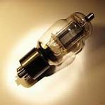
It's a minor thing, but it made me recall the crystal socket that was discovered last Saturday. Went back to my photos and confirmed that the subcarrier oscillator was, in fact, built on a removable chassis. The tube is a 6U8, one RCA used in this circuit in pre CTC2 chassis before introducing the 6AN8. Unfortunately, the name of the builder of this chassis is no closer to being known. The crystal in this photo was from a CTC2.
Pete
|
|
#179
06-24-2011, 01:49 PM
|
||||
|
||||
|
Quote:
There was no crystal INSTALLED, though there is a SOCKET for one.
__________________
Evolution...
|
|
#180
06-24-2011, 01:56 PM
|
|||
|
|||
|
Was thinking you will need to get some sort of power supply to power up sections of the chassis. I think the power supply from one of the many 1948-1950 B&W RCA projection sets would be a good fit. Has three 5U4G, it is an RCA chassis, just about the right period. And there has to be a couple of guys with spare chassis for these.
|
| Audiokarma |
 |
|
|


 Linear Mode

