Videokarma.org

Go Back   Videokarma.org TV - Video - Vintage Television & Radio Forums > Antique Radio

We appreciate your help

in keeping this site going.
Reply
 
Thread Tools Display Modes
  #31  
Old 01-09-2011, 09:54 PM
leadlike's Avatar
leadlike leadlike is offline
VideoKarma Member
 
Join Date: Apr 2008
Location: Lancaster, Pa
Posts: 956
Glad to see it is coming along. In mine, at least one of the bakelite blocks only had a mica cap in it, so I left that one be, as it didn't test as leaky. I'll be curious if you can get the dial to track properly, as mine is about 50kc off on the low end of the dial, the trimmers just wouldn't compensate that far, but reception was excellent, better than a comparable Atwater Kent that I have.
Reply With Quote
  #32  
Old 01-09-2011, 10:56 PM
bandersen's Avatar
bandersen bandersen is offline
RCA 741PCS
 
Join Date: Mar 2009
Location: Chicago, IL
Posts: 8,096
There are several 110 pF micas in the bakelite blocks. I already picked up replacements so figure I'll go ahead and use them. I hope to fire it up in a few days.
__________________
Here are my Vintage Radio & TV YouTube Channel and Photo Gallery
Reply With Quote
  #33  
Old 01-11-2011, 09:07 PM
bandersen's Avatar
bandersen bandersen is offline
RCA 741PCS
 
Join Date: Mar 2009
Location: Chicago, IL
Posts: 8,096
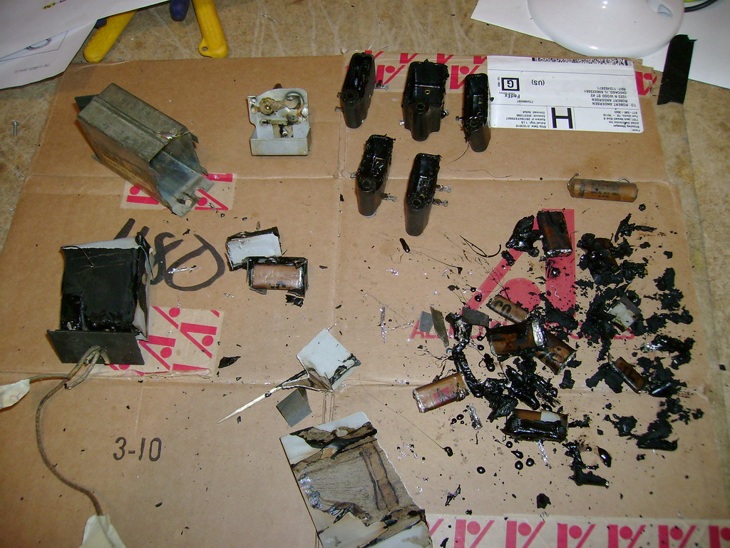
I've finished unmounted and unstuffing all the bakelite block capacitors. Also the tone control and metal box cap.
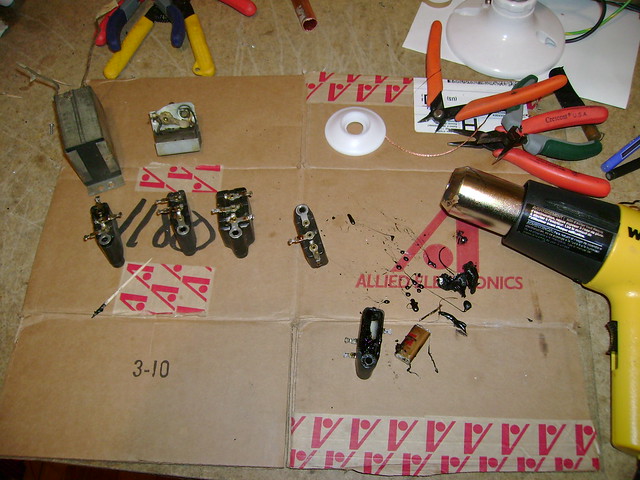


It actually wasn't all that bad. Next, I'll clean up the tubs and mount new caps inside.
__________________
Here are my Vintage Radio & TV YouTube Channel and Photo Gallery
Reply With Quote
  #34  
Old 01-12-2011, 07:29 AM
GuyIncognito GuyIncognito is offline
VideoKarma Member
 
Join Date: Feb 2010
Posts: 33
Hi bandersen,

I just saw your latest video--great stuff, as usual!

If I remember correctly, the depth--and therefore the "mesh"--of the tuning capacitor plates can be easily tweaked using that nut/screw arrangement on the back. It is an adjustment used to change the point at which that single rear ball bears vertically on the end of the rotor shaft. Tightening the screw pushes the ball and rotor forward, and vice versa; the nut locks it in place when everything is nice and centered.

Last edited by GuyIncognito; 01-12-2011 at 07:37 AM.
Reply With Quote
  #35  
Old 01-12-2011, 01:07 PM
bandersen's Avatar
bandersen bandersen is offline
RCA 741PCS
 
Join Date: Mar 2009
Location: Chicago, IL
Posts: 8,096
Quote:
Originally Posted by GuyIncognito View Post
Hi bandersen,

I just saw your latest video--great stuff, as usual!

If I remember correctly, the depth--and therefore the "mesh"--of the tuning capacitor plates can be easily tweaked using that nut/screw arrangement on the back. It is an adjustment used to change the point at which that single rear ball bears vertically on the end of the rotor shaft. Tightening the screw pushes the ball and rotor forward, and vice versa; the nut locks it in place when everything is nice and centered.
Thanks! I'm sure you're right although the nut/screw are pretty well fused together on mine. Luckily the scraping I had was only on one set of plates rather that the whole rotor shaft being out of whack. A little tweak to the position of the fixed plates in that section cleared it right up.
__________________
Here are my Vintage Radio & TV YouTube Channel and Photo Gallery
Reply With Quote
Audiokarma
  #36  
Old 01-13-2011, 12:43 PM
bandersen's Avatar
bandersen bandersen is offline
RCA 741PCS
 
Join Date: Mar 2009
Location: Chicago, IL
Posts: 8,096
I've restuffed the block caps with the aide of all the great info at philcoradio.com
I don't see any point in refilling the tubs with anything since the open side faces the chassis.
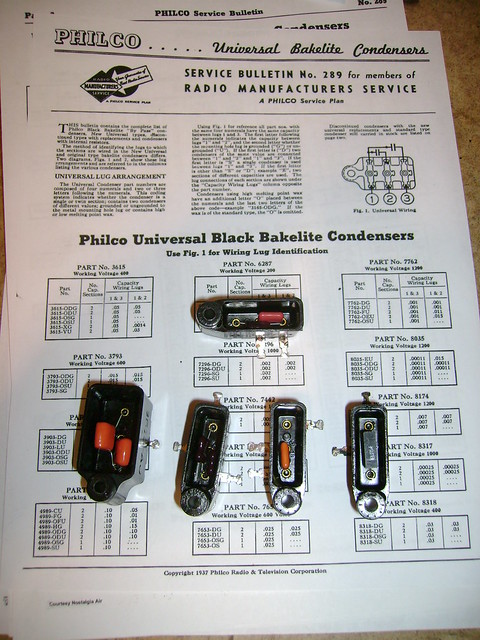


The 8035-D was confusing though. It doesn't match what philcoradio.com showed. It also doesn't follow the usual wiring where both caps are connected to the lug terminal.
Instead, the terminal opposite the lug is the common terminal.
__________________
Here are my Vintage Radio & TV YouTube Channel and Photo Gallery

Last edited by bandersen; 01-13-2011 at 01:37 PM.
Reply With Quote
  #37  
Old 01-13-2011, 08:09 PM
polyphase polyphase is offline
VideoKarma Member
 
Join Date: Nov 2010
Location: New York
Posts: 42
Quote:
Originally Posted by Reece View Post
I'm always harping on this, but I would put a plywood bottom shelf under that speaker all the way to the back of the cabinet to enclose the bottom of the speaker compartment. The way they made them there's an acoustic short circuit from the front to the back of the cone: result, less bass.
I have to agree with this. A 250Hz tone has a wavelength of about 4ft, so at least a partial acoustic short circuit would exist here, right in the critical lower midrange. 100Hz material, if deliverable from this set (I suspect it is), would pretty much be cancelled out.
Reply With Quote
  #38  
Old 01-14-2011, 07:39 PM
Reece's Avatar
Reece Reece is offline
VideoKarma Member
 
Join Date: Jul 2004
Location: Cleona, PA
Posts: 2,178
It would appear that the 8035-D is wired correctly with the mounting lug being the ground end of the .00011 mfd. cap.
__________________
Reece

Perfection is hard to reach with a screwdriver.
Reply With Quote
  #39  
Old 01-14-2011, 09:58 PM
bandersen's Avatar
bandersen bandersen is offline
RCA 741PCS
 
Join Date: Mar 2009
Location: Chicago, IL
Posts: 8,096
Quote:
Originally Posted by polyphase View Post
I have to agree with this. A 250Hz tone has a wavelength of about 4ft, so at least a partial acoustic short circuit would exist here, right in the critical lower midrange. 100Hz material, if deliverable from this set (I suspect it is), would pretty much be cancelled out.
I'll definitely do a comparison with and without once I get it running.

Quote:
Originally Posted by Reece View Post
It would appear that the 8035-D is wired correctly with the mounting lug being the ground end of the .00011 mfd. cap.
Yeah, I followed the schematic so it should be OK.

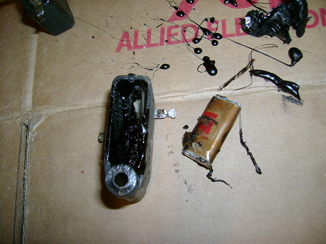
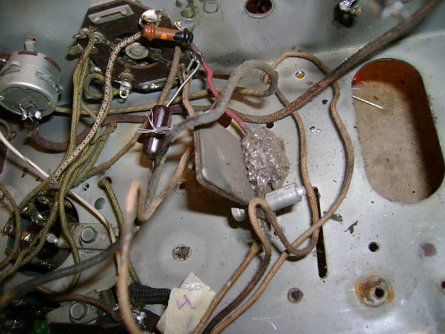
Speaking of schematics, I couldn't find this gooey looking thing on mine. I did a little research and discovered that it's a wavetrap added to later revisions. The bubbling goo appears to be old wax.

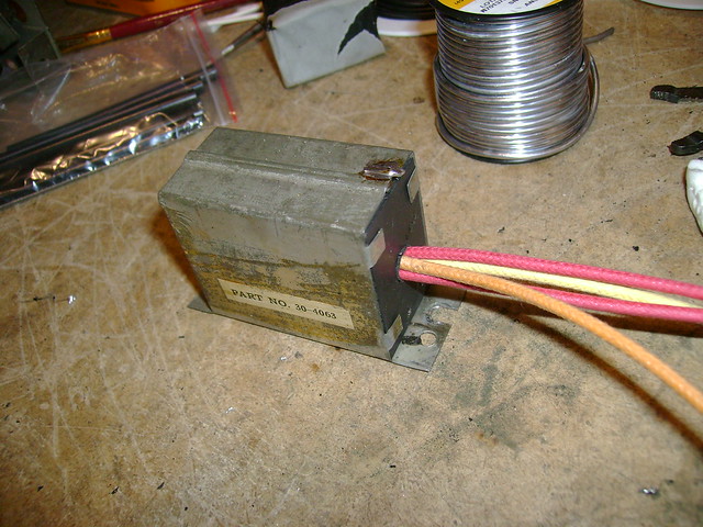
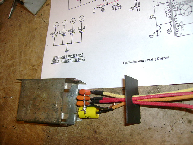
Here's the rebuilt metal box cap.

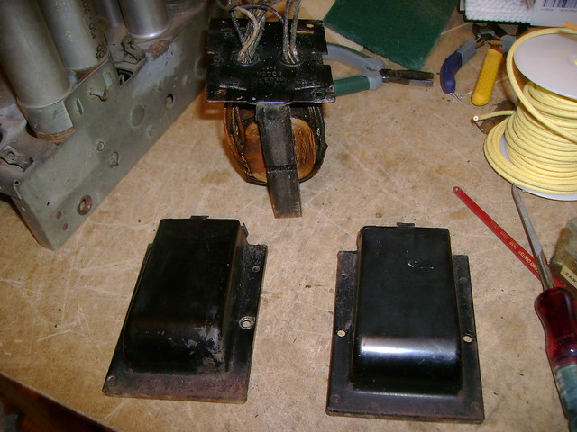
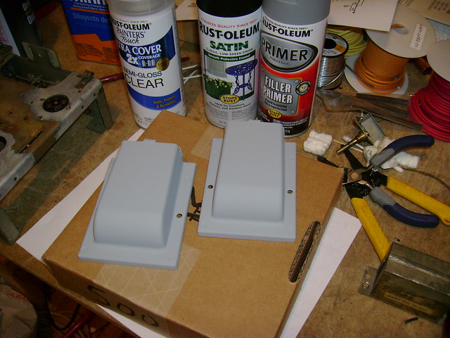
Call me crazy, but I don't like rust. So, I unmounted the power transformer and removed the clamshell covers.
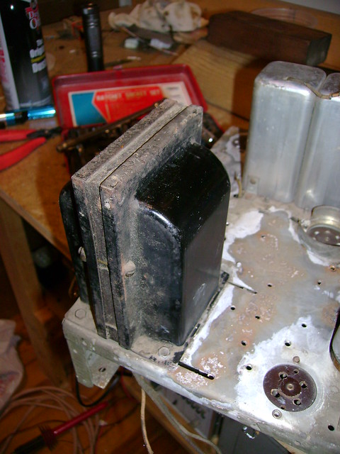

Then, I removed the rust and sanded them a bit.
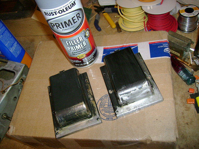

Here they are after some primer. Next up, some black enamel.
__________________
Here are my Vintage Radio & TV YouTube Channel and Photo Gallery
Reply With Quote
  #40  
Old 01-14-2011, 11:53 PM
leadlike's Avatar
leadlike leadlike is offline
VideoKarma Member
 
Join Date: Apr 2008
Location: Lancaster, Pa
Posts: 956
Oh yeah, that web site on the progression of circuit changes in the Philco model 60 is essential. From that, I was able to determine mine was the last revision.

On the Nostalgiaair website, there is an article: The Philco Model 60 Repair That Almost Wasn't, where the poor guy basically goes to recap the thing, says, hey- this radio has some weird changes, and alters his Philco back to the original style, only later realizing that those changes were intentional!
Reply With Quote
Audiokarma
  #41  
Old 01-20-2011, 05:23 PM
bandersen's Avatar
bandersen bandersen is offline
RCA 741PCS
 
Join Date: Mar 2009
Location: Chicago, IL
Posts: 8,096
Ouch! I've taken loads of photos and taken notes so I should be able to get it back together properly.

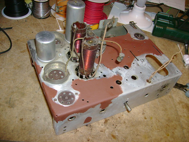
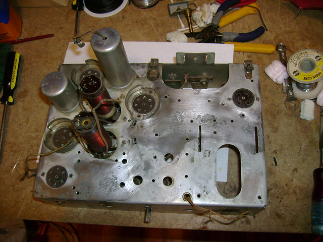
I finally got all the rust off the chassis then applied some Rustoleum "Rusty Metal Primer". I'll go a few rounds of sanding and primer to fill in the pits.
The cadmium plating was fine in the unpainted areas.

I also popped out the two rivets holding on the IF coil shields so I can replace the rotting grid cap lead. It makes it easier to paint around too.
__________________
Here are my Vintage Radio & TV YouTube Channel and Photo Gallery
Reply With Quote
  #42  
Old 01-24-2011, 11:48 PM
bandersen's Avatar
bandersen bandersen is offline
RCA 741PCS
 
Join Date: Mar 2009
Location: Chicago, IL
Posts: 8,096
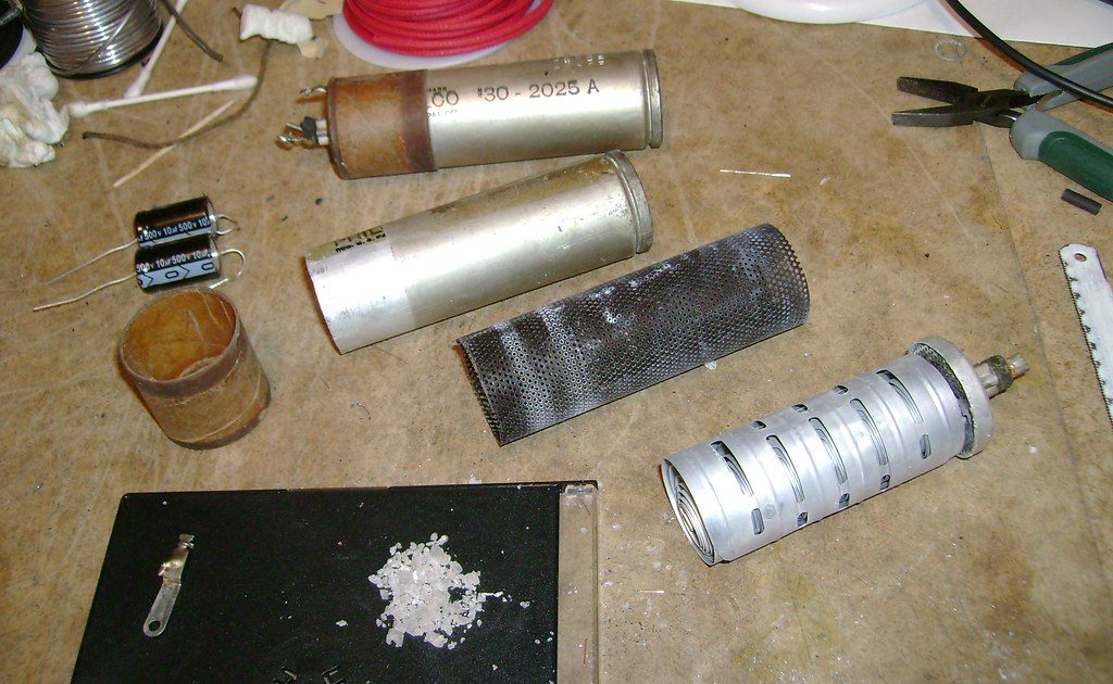
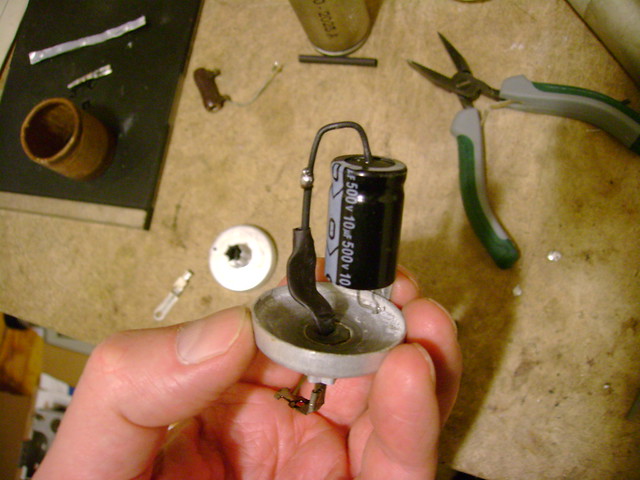
The original electrolytics are rated 8uF @ 475 VDC. I'm using 10uF @ 500 VDC. I think that will be close enough.

I cut the ends open using a hacksaw and found this inside.
I wonder what compound those crystals are ? Nothing horribly toxic I hope
__________________
Here are my Vintage Radio & TV YouTube Channel and Photo Gallery

Last edited by bandersen; 01-24-2011 at 11:51 PM.
Reply With Quote
  #43  
Old 01-25-2011, 12:13 AM
compu_85's Avatar
compu_85 compu_85 is offline
Procrastination Expert
 
Join Date: Sep 2010
Location: La Conner, WA
Posts: 281
What is electrolyte usually made out of? I'd imagine it's not too dangerous as long as it's dry and you don't eat it

-J
Reply With Quote
  #44  
Old 01-25-2011, 06:41 AM
Reece's Avatar
Reece Reece is offline
VideoKarma Member
 
Join Date: Jul 2004
Location: Cleona, PA
Posts: 2,178
It's borax. Not bad at all.
__________________
Reece

Perfection is hard to reach with a screwdriver.
Reply With Quote
  #45  
Old 01-26-2011, 03:06 AM
bandersen's Avatar
bandersen bandersen is offline
RCA 741PCS
 
Join Date: Mar 2009
Location: Chicago, IL
Posts: 8,096
Quote:
Originally Posted by Reece View Post
It's borax. Not bad at all.
Ah, good to know.

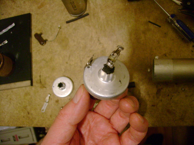
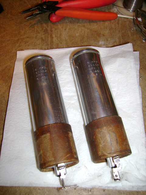
I pretty much rebuilt these the same way as Phil Nelson. I did drill a small hole for the negative lead though.
After feeding the lead through, I wrapped it around the old terminal and soldered it. Originally, it made contact with the can just by pressure.

The decals were already worn off one can so I didn't mind polishing them up. While doing so, I noticed that one can is stamped 61115 and has a flat top while the other is 61116 and has a rounded top.
The 61116 can also had some liquid remaining inside so maybe it's a really old replacement ?
__________________
Here are my Vintage Radio & TV YouTube Channel and Photo Gallery

Last edited by bandersen; 01-26-2011 at 03:12 AM.
Reply With Quote
Audiokarma
Reply


Thread Tools
Display Modes

Posting Rules
You may not post new threads
You may not post replies
You may not post attachments
You may not edit your posts

BB code is On
Smilies are On
[IMG] code is On
HTML code is Off

Forum Jump


All times are GMT -5. The time now is 04:01 AM.


Powered by vBulletin® Version 3.8.4
Copyright ©2000 - 2024, Jelsoft Enterprises Ltd.
©Copyright 2012 VideoKarma.org, All rights reserved.