
|
|
|
#46
 08-24-2017, 03:24 PM
|
|||
|
|||
|
Quote:
Quote:
Quote:
Do you think this is related to the AGC or do I have two unrelated problems? Thanks for the suggestions -- will get to work on those next and let you know. FK 
|
|
#47
08-24-2017, 03:54 PM
|
||||
|
||||
|
If the noise goes away completely with the IF tubes pulled then the problem is either up stream of the 1st IF tube you can pull to kill the noise or it is in the AGC.
If the noise goes away with the 1st IF tube pulled, then odds are it is in the tuner, or it is local interference. If you have a signal source that operates on other channels than the one your currently using it may be wise to try different channels. There is a large gap (FM band + other stuff) between channels 2-6 and channels 7-13. So switching from low band VHF to high band or vice-versa may be a wise test (to get away from wide band noise). Also if a local DTV channel is using the same RF carrier freq as your signal source, you will likely get noise from that DTV carrier leaking into your set. One way you can eliminate AGC noise is to connect the AGC buss to an external adjustable DC supply 0-25V and use that supply to clamp the AGC line to a proper fixed voltage.
__________________
Tom C. Zenith: The quality stays in EVEN after the name falls off! What I want. --> http://www.videokarma.org/showpost.p...62&postcount=4
|
|
#48
08-25-2017, 10:56 AM
|
|||
|
|||
|
Quote:
Quote:
Here's what I'm seeing now with VA62 feeding channel 3 RF: https://youtu.be/q8nD70vokkE It's odd that the audio takes hits too because it's picked off immediately after the detector which is basically right after the IF injection point that I used. Would this seem to suggest the issue is in fact HV-related since that would be about the only thing remaining that could cause this effect on both audio and video? Quote:
There are otherwise no voltage readings called out on the schematic for that portion of the circuit so I'm confused as to where this negative voltage would be normally developed? I should expect to see that same between -9 (or so) and 0V at that point if everything was working correctly yes? Thanks! FK
|
|
#50
08-25-2017, 12:59 PM
|
|||
|
|||
|
Quote:
http://antiqueradios.com/forums/view...p?f=3&t=201711
|
| Audiokarma |
|
#51
08-25-2017, 01:06 PM
|
||||
|
||||
|
I second what JR said.^
Given that with the 3RD IF pulled and the signal injection after that, that the interference remains. The problem is most likely noise in the B+ or HV arcing. There could be issues in the stages between the video detector and the CRT, but it is not as likely. Since you are getting sound interference too, here is an idea to save you some time....Pull the H output tube or damper (to stop supply of HV) and see if the sound interference goes away after it has had a couple of minutes to run without HV (you obviously can't check picture with no HV). If disabling the HV stops the interference then the issue should be in the HV or CRT grounding. If the noise remains without HV then check the B+ lines with a scope, and if those are clean use the scope to look at the stages between the injection point you were using and the CRT video feed. You may have AGC issues, but if as you say the IF is passing signals properly (with the exception of the mystery noise), then I'd ignore the AGC until the noise issue is fixed. The AGC appears to only affect the tuner, 1ST and 2ND IF...So given you can inject after the 3RD IF with the 3RD IF tube pulled and still get noise, I think it is safe to say the AGC is not your noise source, and can be ignored for now.
__________________
Tom C. Zenith: The quality stays in EVEN after the name falls off! What I want. --> http://www.videokarma.org/showpost.p...62&postcount=4
|
|
#52
08-25-2017, 01:08 PM
|
|||
|
|||
|
Quote:
Quote:
FK
|
|
#53
08-25-2017, 01:22 PM
|
||||
|
||||
|
Quote:
__________________
Tom C. Zenith: The quality stays in EVEN after the name falls off! What I want. --> http://www.videokarma.org/showpost.p...62&postcount=4
|
|
#54
08-25-2017, 01:47 PM
|
|||
|
|||
|
One way to test for questionable dag grounding is tape on a grounding wire, and see if the noise disappears. Strip several inches of insulation off a piece of hookup wire and tape it to the dag, and the other end to ground.
That's assuming there's no isolated patches or 'islands' of dag lurking around, which happens occasionally. Last edited by old_coot88; 08-25-2017 at 01:54 PM.
|
|
#55
08-25-2017, 02:57 PM
|
|||
|
|||
|
You might want to be careful using tape to hold a wire against the dag. The dag is not known to have very good adhesive characteristics and you might pull off a big amount of dag when you remove the tape.
|
| Audiokarma |
|
#56
08-25-2017, 04:10 PM
|
|||
|
|||
|
Quote:
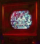
Now here's the thing... before that, after playing a bit with the suggestion of grounding out the 3rd IF with a cap, and working with DC on the AGC circuit, the noise seems to have gone away... along with decent picture contrast. It's possible that it could have been poor contact with that rubbed-off dag and in working on the chassis the contact was intermittent. So without a clear explanation, I seem to have a more or less clean but poorly contrasted image. As with before, it looks brighter in the video than in person. https://youtu.be/xWOoI252aZY There is definitely some wobble to the picture as well, which you can see with the DTV but can see it much better with the test pattern. I'm adjusting first the fine tuning then the brightness then the contrast and you can see there's not really a sweet spot. https://youtu.be/XO5ciFJxHiM Since the CR70 rejuv, the tube now produces a lot of light with brightness all the way up. I re-checked it again and still has responsive cutoff and gets up to about a 10.5 on the CR70 emissions when it's warm. Still nothing on the AGC control, but injecting negative or positive DC doesn't make any large improvement to the picture's contrast so maybe that's just not going to be a big help. I would say contrast and vertical hold tends to get worse as the set warms up. The sound (as can be heard in the test pattern video above) get very soft when the channel is fine tuned in for best picture. I know this is typical with old B&W sets and cheap DTV boxes though. Just got the HV probe and it's measuring 15kV, while the schematic calls for 17.5k. I'll try a few different horiz damper and output tubes and see if that makes any difference. FK
|
|
#58
08-25-2017, 07:08 PM
|
|||
|
|||
|
Quote:
Edit: Turning width control all the way up and brightness/contrast all the way down, I've got 17.6kV so HV seems solid. FK Last edited by FrankieKat; 08-26-2017 at 04:13 PM.
|
|
#59
08-25-2017, 07:23 PM
|
|||
|
|||
|
Quote:
|
|
#60
08-26-2017, 05:05 PM
|
|||
|
|||
|
So here's the update in quick bullet points.
What's working:
At this point, is there anything else this could be other than those tubes or anything else I could try? Thanks again everyone, for all of your help and great suggestions! FK
|
| Audiokarma |
 |
| Thread Tools | |
| Display Modes | |
|
|


 Linear Mode

