
|
|
|
#16
 02-23-2013, 10:42 AM
|
||||
|
||||
|
There is a producer of bezels (old time reproductions? in CA) for Philco radios that sells through Radiodaze. Maybe they would comission one.

|
|
#17
02-23-2013, 10:59 AM
|
|||
|
|||
|
I'd go for it...a bit pricey,..but worth it
 let me know when ones available let me know when ones available Jody Jody
|
|
#18
02-23-2013, 11:58 AM
|
||||
|
||||
|
That would be worth having a new bezel made by CAD/CAM, and I bet it could be done on a low production scale. I know a hobbyist who is recently retired from a career in mil-spec machining, and he has "made" perfect reproduction laser-cut pocket watch parts, antique car parts, etc. He could probably do it, but I'd have to get his permission to give out his name. He just spent more on a hobby workshop in his barn, than it would cost to build a whole 5000-square foot house. He installed all the technology he knew at work, and has it all set up.
Charles
__________________
Collecting & restoring TVs in Los Angeles since age 10
|
|
#19
02-23-2013, 02:31 PM
|
|||
|
|||
|
There may be a 3D printing option on the bezel, too. But no-one knows if that stuff will last 70 years, either.
I'm not any kind of qualified restorer, but that won't stop me from sharing a thought: Perhaps a thin sheet (1/16" or less) of aluminum, brass, etc. in the original outline of the bezel, with the original bezel aligned as required and mounted to the 'shim'. Paint to match original bezel as much as possible. Attach shim to original wood holes, (hiding the finish issue) and attach bezel to shim in a manner that allows 'creep' without 'crack'. That may be black plastic or nylon phillips machine screws in to tapped holes or soldered-on threaded plates, or the like. The plastic/nylon would give a bit, allowing original bezel to move without cracking more. If the black nylon screw head looks out of place, then perhaps use a flat-head screw and affix a sacrificial black steel phillips head (only) to it... basically as decoration. Yeah it's a lot of work, but you've got a pretty good head start overall! Nice example. Chip
|
|
#20
02-23-2013, 03:25 PM
|
||||
|
||||
|
I would put in a plea to at least ATTEMPT to do an electrical restoration, as well...You might get lucky & end up w/a WORKING pre-war TV...How KEWL would THAT be ?!?
__________________
Benevolent Despot
|
| Audiokarma |
|
#21
02-23-2013, 07:34 PM
|
||||
|
||||
|
Quote:
Last edited by vts1134; 02-24-2013 at 06:24 AM. Reason: Typo
|
|
#22
02-24-2013, 06:55 AM
|
||||
|
||||
|
I was able to find some date code info on the net. I could only find out what the first two digits of the three digit code stand for. Every tube in both the radio and television chassis, except for one, are RCA branded and coded KE5, XE1, XE2, or XE3. That means 1938, and 1939 OEM for the first two digits, does the last number indicate month? The only exception in the set is the horizontal output tube which is branded National Union. The only coding I can find on that tube is an "F". I don't have a tube tester so I don't know how well used they are, but maybe the set was used so little that the tubes are all original?
|
|
#23
02-24-2013, 06:58 AM
|
||||
|
||||
|
Quote:
Last edited by tubesrule; 02-24-2013 at 07:15 AM.
|
|
#24
02-24-2013, 07:05 AM
|
||||
|
||||
|
Quote:
Last edited by tubesrule; 02-24-2013 at 07:16 AM.
|
|
#25
02-24-2013, 07:12 AM
|
||||
|
||||
|
Quote:
Ed has investigated 3D printers but none of them give a good surface finish so the entire part would need to be sanded and polished (if the material is hard enough to accept a polish) and if it is intricate this can be difficult if not impossible. CNC can't make these swirled plastic parts unless you can find some swirled plastic material to start with. A CNC part could be used by Ed or Larry to then make a mold to cast parts, but even a CNC part takes considerable amount of sanding and polishing to create the mirror finish.
|
| Audiokarma |
|
#26
02-24-2013, 07:35 AM
|
||||
|
||||
|
Reproduction pushbuttons are available here:
http://www.renovatedradios.com/parts.html#pushbuttons There are a number of RCA radios that use similar bezels. The difference is that the TRK-5 bezel uses aluminum pieces around the eye tube and electric tuning light, while the bezels from other RCA radios either have no pieces or have pieces that are silver. It is easy to remove the painted pieces from the old bezel and put them on the replacement bezel, though. Here are some of the RCA radios with similar bezels: 98T, chassis RC-386A 98K2, chassis RC-386A 97K2, chassis RC-351K 97T2, chassis RC-351K 96E2, chassis RC-351L 96K5, chassis RC-351L 96T7, chassis RC-351L Last edited by Steve McVoy; 02-24-2013 at 08:15 AM.
|
|
#27
02-24-2013, 08:36 AM
|
|||
|
|||
|
Hi All;
VTS1134, You should be able to find another member in the Area of where you live who has a tube Tester, that could help you, determine how good the tubes are.. I have one that would do the trick but I live way tooo far away.. THANK YOU Marty
|
|
#28
02-24-2013, 09:34 AM
|
||||
|
||||
|
Marty-
I have a local shop in my area where I test all of my tubes so I'm covered there. I have the reproduction pushbuttons ordered and they are on the way. Since I have to wait for the pushbuttons to arrive before I install the radio chassis and bezel, I'll put that on the back burner. On to the television chassis. Looking over the underside of the chassis I can see that there was repair work done to the horizontal output circuit. That could account for the replacement horizontal output tube. 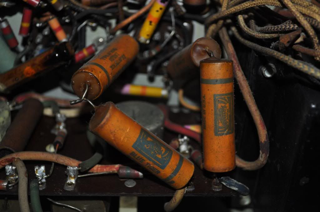 Can any one spot anything else out of place? 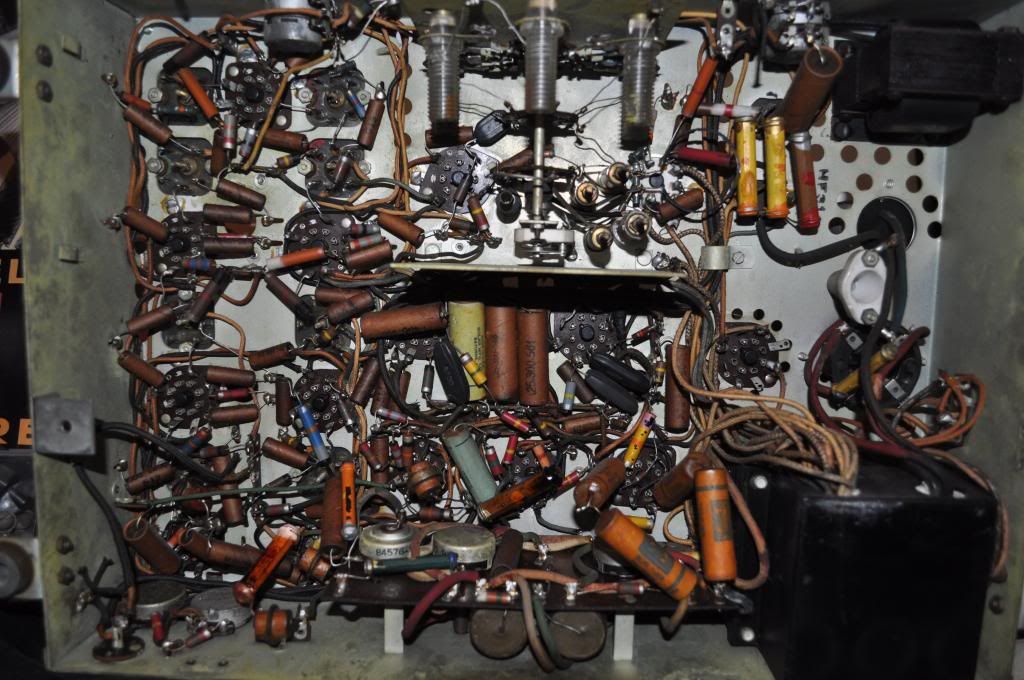
Last edited by vts1134; 02-26-2013 at 10:29 AM.
|
|
#29
02-24-2013, 09:59 AM
|
||||
|
||||
|
The television chassis has suffered some damage. The fine tuning portion of the channel selector shaft has broken off.
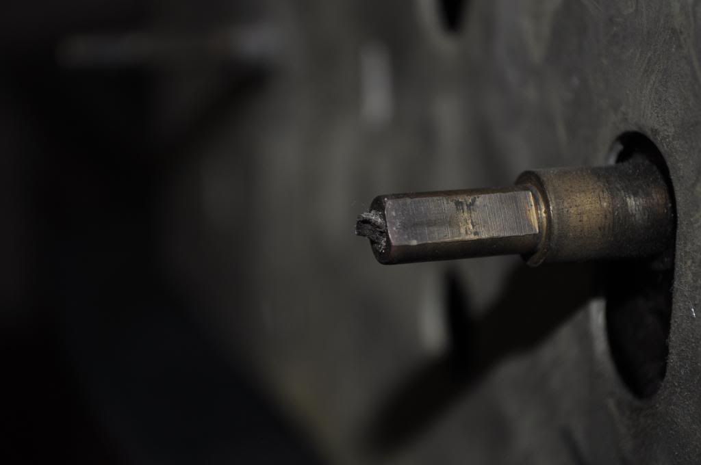 I am able to turn the fine tuning control from what's left of the shaft, however it simply spins freely, the shaft must be broken internally as the fine tuning capacitor (C9) does not move. I thought perhaps the capacitor could be seized, which would account for the breakage, but I can adjust it manually. 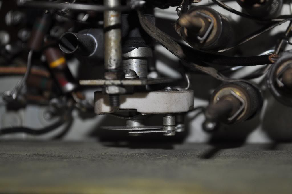 I am considering a repair to this part of the set depending on difficulty, and whether or not an original shaft can be found, or the original repaired.
|
|
#30
02-24-2013, 11:34 AM
|
||||
|
||||
|
John,
Those replaced caps are the horizontal deflection coupling caps and are always bad. They did take a while to go bad originally which suggest this set was used for quite some time. It's too bad that the original caps are gone as it's quite easy to restuff them with modern 3000V caps. You'll need to find caps of the correct size or cardboard tubes that can be dyed to match to use for restuffing. The two large caps on the opposite side of the board with the yellow and green heavy wires going between them are the vertical deflection coupling caps are are most likely bad. Your fine tuning control is working correctly. The shaft is supposed to turn freely. If you look at your picture of the trimmer cap, the aluminum piece on the end is cup shaped. The black rubber piece is attached to the end of the brass shaft that goes through the main tuning shaft and is shaped to fit the cup. To adjust the fine tuning you have to push in on the shaft to make the rubber piece turn the trimmer cap. The fine tuning shaft can be fairly easily replicated although it's a little difficult to install since it's rather long and you have to remove the trimmer to get it in.
|
| Audiokarma |
 |
|
|


 Linear Mode

