
|
|
|
#32
 10-30-2014, 07:20 PM
|
|||
|
|||
|
if the .12 was bad, then its ok, if it was not bad then its still ok, just not needed. Recapping as a way to fix problems is not a good idea. You may get lucky but you learn nothing. Better to learn how things work the diagnose the problem, esp with sets of this era, the caps are often fine, and recapping just introduces the possibillity of errors (wrong values broken traces etc..)
Besides what do you do after recapping and you still have a problem, or if it works for a year then a new problem, recap all again? so learning how things work is the way to go and what I think this forum can help you with. Last edited by DaveWM; 10-30-2014 at 07:23 PM. 
|
|
#34
10-31-2014, 03:39 AM
|
||||
|
||||
|
Quote:
__________________
"Face piles of trials with smiles, for it riles them to believe that you perceive the web they weave, and keep on thinking free"
|
|
#35
10-31-2014, 08:08 AM
|
||||
|
||||
|
great video and i found the cap and resistors as far as the disc i will have to change it because i have no way to positively check it and what is the voltage on that .01 disc cap? the resistors on the other hand well the 68k was found to be 69.8k and the 100k was found to be 100.8k both of which is well within range. so now if i can find out what the voltage rating is for the .01 disc ill change that just to be sure . the doubler caps being i have 4 in paralle 3 of which are the same brand but the 4th one is smaller and a different brand so i have 2 caps rated 450v 470uf i was going to put in place of what i have now and while it is a bit overkill at least they are both the same and there will only be 2 of them, just to rule out any possible problem with the ones in there now. im still debating weather or not i should leave the 2 caps in paralle that are .022 and .1 for the .12 that was in the set originally there are certain opinions about doing this with caps because one could go bad and pull down the circuit that its tied to so i would figure this could do away with any possible future problems since i dont have a cap tester on hand.
|
| Audiokarma |
|
#36
10-31-2014, 09:18 AM
|
|||
|
|||
|
I would say anything rated more than 100v on the .01 should be fine. That being said its very UN likely to be the problem. Disc caps are very reliable.
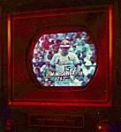
I did some more checking on my set, the one in the video with the problem. . The CRT would not produce any lines in setup mode unless i advanced the red gun fully CW and then advanced the bias pot about 1/4 of the way. I tested the CRT with my CR-70 and it tested quite weak (well into the red zone) with very little cut off response. So with that I presume my issue is a weak CRT (its not very bright either). I suggest you try checking your CRT again, and if confirm that the CRT tester is working properly. IF your CRT is good with a known good CRT tester, you should also consider checking the filament voltage at the CRT just to make sure the filaments are getting the correct voltage from the set. Again this is a long shot. remember CRT testers are not infallible, just cause it says its good does not mean it is. The only way to be sure would be to check the calibration of the tester OR test it on a known weak CRT to confirm its function. Before messing with the power supply caps you should just check the B+ voltage to see if its what it should be with a multimeter. I doubt a B+ fault would be causing the issue.
|
|
#37
10-31-2014, 10:36 AM
|
||||
|
||||
|
well i do have another set round screen with a very weak red gun the others are not that great either however i also have 2 more crt testers and get the same from the weak crt. and the set with the weak crt has a perfect picture and clear no lines, even though i have video issues with that one it still has a good pic. so with these testers i will go ahead and check this crt and the cutoff again but if it should show good cutoff i dont know where i will go from there. it certainly to me sounds like you know a whole lot more about these sets then i will ever know. on my bk440 which i have 2 of them and one is recapped and the cutoff the last time i checked on both showed the same and where it has the line on the right and left the test on all the guns were less then half on that scale but not at the quarter line but rather higher then the quarter itself.
|
|
#38
10-31-2014, 02:56 PM
|
||||
|
||||
|
Quote:
A little refresher on series & parallel capacitors: http://www.coilgun.info/theorycapaci...apacitors2.htm jr
|
|
#39
10-31-2014, 06:46 PM
|
||||
|
||||
|
Quote:
|
|
#41
10-31-2014, 08:44 PM
|
|||
|
|||
|
you can use a foil cap in place of the disc.
You do not need to remove tubes to check the B+ just find a B+ test point on the chroma board and turn it on, wait for raster to come up and see what it is.
|
|
#42
11-01-2014, 08:04 AM
|
||||
|
||||
|
yes i know i could do that but with the chassis in but right not its out of the cabinet i didnt know if it would have been helpful to check it out of the cabinet with the hot out but it does pay to do it with all hooked up. so ill stick with the disc as whats in there, as a replacement. i also checked the 2 1.5 meg resistors that are for the hv some say they must be matched i really dont know but 1 is 1.509 and the other is 1.602 dont know if this would have any bearing on the hv issue.
|
|
#43
11-01-2014, 08:57 AM
|
|||
|
|||
|
those effect the HV regulation circuit. No reason to suspect them unless you know the HV reg circuit is not working.
To know that you need to test it, using the shunt on the 6Bk4 and see if the current thru the tube varies with HV pot setting AND CRT brightness. You should get between .5 and 1.5 ma current from high to low brightness (raster). this will vary depending on the HV setting, typical is 23-25kv and should hold to within 500v when vari brightness (the shunt tube draws more current when the screen is dark, keeping the HV in check as the CRT load drops. as the brightness increases so does the currrent thru the CRT and the shunt tube current drops, this keeps the flyback HV total current and HV voltage constant). I don't think you can check them for value in circuit and get accurate results as to how closely matched they are. I do not recommend replacement unless there is a KNOWN problem in that circuit.
|
|
#44
11-01-2014, 12:43 PM
|
||||
|
||||
|
i did clip one end of the 1.5 meg resistors and got the reading above. i was told if i have to i could use 2 1meg ohm instead and it would change something minor with the hv adjustment but would still do what it has to. i still have the unknown problem with hv regulation and this is why i was wondering how important those resistors really are.
|
|
#45
11-01-2014, 12:59 PM
|
|||
|
|||
|
Quote:
do this, check the HV with a probe with the CRT brightness all the way down, does the HV pot adjust from say 20 to 27kv? If it does the regulator tube is working. now set the HV to 23kv with the brightness all the way down. READ the shunt tube current and let me know what it is. Based on what you get I will tell you what do do next.
|
| Audiokarma |
 |
|
|


 Linear Mode

