
|
|
|
#196
 06-27-2011, 02:08 AM
|
||||
|
||||
|
Interesting reads, IS THIS an electronic version of the later and cheaper color wheels or similar with color phase shift?
__________________
1977 Zenith Chromacolor II A Very Modern Zenith 
|
|
#197
06-27-2011, 11:13 AM
|
||||
|
||||
|
Nope. Color wheels work with sequential fields of color which is a different principle entirely.
__________________
tvontheporch.com
|
|
#198
06-27-2011, 12:12 PM
|
||||
|
||||
|
I have attached another version. The drawing is sideways: at least it is better than upsidedown.
It is interesting to put this paper on CPA in context with the development of the all-electronic compatible color. By mid 1952, much of the development of what would finally end up in the December 1953 standard was there. The constant luminance principle was there as was the chrominance quadrature modulated on a odd multiple of half line frequency to facilitate luma/chroma interleaving. But also the elements which would soon disappear including the burst pedestal as was assymetrical B-Y and R-Y bandwidths and the higher subcarrier frequency. It is interesting that the original RCA RGB Dot Sequential sample frequency is fairly close to the later NTSC subcarrier of 3.58MHz. The original impetous for CPA was to extend the bandwidth of the chroma channel within the limited bandwidth of the US 6MHz wide channel. Hence the choice of 3.9MHz for the CPA subcarrier I suggest was for two reasons: to provide wider bandwith (vestigial sideband chroma) for both R-Y and B-Y and to extend the luma channel response. Remember that there is a luma 3.58MHz trap in early NTSC receivers which effectively cuts the high frequency luma response to 3MHz or less. A 3.9MHz chroma subcarrier would have extended the luma response a little bit. CPA employed for PAF or PAL (Phase Alternate Field or Phase Alternate Line)was simply inverting the R-Y axis at either field rate or line rate. The reason for doing so was to eliminate differential phase errors which would result in hue errors and to cancel quadrature crosstalk between R-Y and B-Y at demodulation. Remember, crosstalk was eliminated with I and Q by ensuring both were double sideband to 500kHz and only I extended from 500kHz to 1.5MHz. CPA facilitated vestigial sideband R-Y and B-Y and the crosstalk was to be cancelled by averaging. In 1952 only visual averaging of the PAF and PAL was available which led to the crosstalk and hue errors resulting in the annoying field flickering (PAF) and a vertical line crawl (PAL). The European engineers later termed the PAL line crawl as "Hannover Bars" and may be readily seen on what is referred to as "Simple PAL" decoders or PAL decoders without the electronic delay line averaging. In 1952, the NTSC was exploring PAF as the field flickering was deemed less objectionable to the line crawl. I agree with the later NTSC assessment that moving away from the CPA to the I Q solution was one step beyond CPA in the development of compatible color TV. Successful deployment of CPA with PAL fifteen years later depended upon the one-line delay line which was not readily available in 1952. We should look forward to finding out what remains of the CPA circuitry in this extremely unique prototype. I trust you will share with us the circuit as you trace it. I am particularly interested in the CPA transformer: the alternating R-Y phase I feel would have been derived from reversing at field rate either the chroma before demodulation or the regenerated subcarrier used for R-Y demodulation. I suspect the transformer is in the chroma signal path as per the diagram in the attached article? Last edited by Penthode; 06-27-2011 at 12:19 PM.
|
|
#199
06-27-2011, 03:38 PM
|
||||
|
||||
|
Quote:
Actually it's closest to the subcarrier oscillator, so right now my assumption is if flips the reference signal 180 degrees on alternating fields for R-Y. Only time will tell for sure, this coming weekend we are hoping to delve into the demod sections in order to figure it out. Tim did spot an odd part that I hadn't previously seen: right near the CPA tranformer hidden under some variable capacitors there is a toroid with 2 or 3 windings on it. It's about an inch and a half in diameter, and looks to have something like #30 wire wrapped around it. We have absolutely no idea what its purpose could be.
__________________
Evolution... 
|
|
#201
07-05-2011, 12:20 PM
|
||||
|
||||
|
Patience, grasshopper. There is some discussion going on behind the scenes with the early color guys, I don't want to release any information until I am sure of what I'm looking at (to avoid confusion). Right now, I have most of the chassis schematic sketched out on paper. Once the rest of it is done it will be transferred to computer graphics so it's easy to read, and I'll post it up here for all to see. I still need a couple weeks to get it all finished up, only deflection and a few random pots remain...
__________________
Evolution...
|
|
#203
07-05-2011, 07:13 PM
|
|||
|
|||
|
A little confusion is a fundamental quality in a good Forum.
|
|
#204
07-05-2011, 07:41 PM
|
|||
|
|||
|
It's just that the only thing that to me that could be as interesting or as suspensfull (Did I spell that rite?) as this adventure would be some un-earthed Zenith color proto's or documentation showing the evolution of Robert Adler's beam deflection color demodulation circuitry!

|
|
#205
07-05-2011, 08:51 PM
|
||||
|
||||
|
Quote:
James
|
| Audiokarma |
|
#206
07-10-2011, 10:32 PM
|
||||
|
||||
|
My brother Tim stopped by on Saturday, and I gave him the paper copy schematics. Being that there are folks on here who have an interest in viewing what we have written down to date, I asked if he could 'computerize' everything we have so I can upload it. A number of people I emailed the paper scans to made comments to the effect that it's just too hard to interpret, and I have to agree. For example, just the IF section takes up close to 3 sheets of regular printer paper.
As soon as he has everything in order, I will post the result here. We are hoping to have it done by the coming weekend.
__________________
Evolution...
|
|
#207
07-11-2011, 12:07 AM
|
||||
|
||||
|
It is nice to hear of your progress with the documenting of your color prototype TV chassis. I look forward to learning more.
__________________
Chris Quote from another forum: "(Antique TV collecting) always seemed to me to be a fringe hobby that only weirdos did."
|
|
#209
07-14-2011, 03:09 AM
|
||||
|
||||
|
Ditto, me, too, even if I don't understand a lot of the "Tech" stuff...I sorta get the general "Gist" of it-I think, anyway, but that's about it...
__________________
Benevolent Despot
|
|
#210
07-23-2011, 09:37 PM
|
||||
|
||||
|
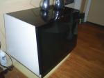
No schematics yet, but there is a power supply!
Might have a potenial power supply, it's from an old organ. Thanks to Bob G for the parts. Top transformer is the B+ stuff, bottom is filament only.
 Should have enough power to do the job, I think. Should have enough power to do the job, I think. 
__________________
Evolution...
|
| Audiokarma |
 |
| Thread Tools | |
| Display Modes | |
|
|


 regards, tommy


 Linear Mode

