
|
|
|
#1
 11-19-2023, 03:42 PM
|
|||
|
|||
|
Zenith Color Roundie Alignment with B&K 415
Looking for some help and hope maybe this thread will help others in the future. I have repaired a Zenith 25MC33 chassis to working condition. I would like to go through the exercise of alignment, or at lease the motions to see where it is at. I understand care is needed and there is risk of making things worse. With that out of the way I have the SAMS folder and the Zenith CM-106 service manual, also the B&K 415 instruction Manual.
I am trying to start with IF and Trap alignment but immediately am stuck. Probably a simple setup mistake but so far I get no measurable signal on the oscilloscope. Making changes to the B&K 415 has no affect. Per the instructions here is what I have done:
The last pic is measuring at test point C1 while operation normally with a cross hatch video signal. B&K 415 Setup     Zenith CM-106 Directions    Scope: 

|
|
#2
11-19-2023, 04:09 PM
|
||||
|
||||
|
Hard to tell, but maybe you have the scope sweep set way too fast? The sweep generator should be sweeping about 60 times per second, so the scope sweep should be around 1 or 2 msec/div. Best is not to use the internal horizontal sweep of the scope, but set up for X-Y operation, with the "too scope horizontal input" of the sweep generator for X.
|
|
#3
11-19-2023, 05:01 PM
|
|||
|
|||
|
old_tv_nut, thanks for the quick reply and suggestion. This leads to more questions. My apologies for the very basic questions, I am in completely uncharted territory.

|
|
#4
11-19-2023, 06:21 PM
|
|||
|
|||
|
Watching Shango work on TV alignment with a B&K 415 and it looks like he has the "To Scope Horz Input" connected to the A Trigger scope input via a simple dual banana to bnc connector. Video here: https://www.youtube.com/watch?v=CmEyYAjjsn0&t=992s. Here is maybe a connector adaptor I could use: https://www.pasternack.com/banana-ja...-pe9011-p.aspx
I'm still not sure when I would then also use the "To Scope Vert Input" coming out of the B&K 415.
|
|
#5
11-19-2023, 07:07 PM
|
||||
|
||||
|
First what ever you do is FLAG you alignment tool with a piece
of tape so you can go back to the start !!!! Write down the turns CW or CCW as you go. It shouldnt take much, like <1/2 turn. Traps can be adj with an OTA signal ( 41.25, 4.5 etc) Now the dirty truth. I was in the TV biz from 1970 til the end of CRT's I never did an alignment. Only one tech I knew in the area did one just to say he did. I may have seen ten sets ever that needed it. A few had a damaged transformer & got eye balled. A few more got tweaked but not by a tech. A few others were real Emersons built in the mid - late 60's. Total toilet sets ! good luck Zeno  LFOD !
|
| Audiokarma |
|
#6
11-19-2023, 07:46 PM
|
||||
|
||||
|
You do not need any scope probes, but you do need cables with connectors that fit the B&K
The way the B&K works is as shown in its diagram. Instead of connecting a scope probe to the TV detector test point, you connect the B&K direct probe to the TV detector point. The B&K then adds the frequency markers to that waveform and outputs the combination of sweep waveform and markers to the B&K connector labeled "To Scope vertical input." Connect this to the scope Y input Connect the B&K connector labeled "To Scope Horizontal Input" to the scope X input. The alignment procedure you posted assumes that you have separate sweep and marker generators, but with the B&K they are combined internally and you do not need the resistor and capacitor assembly shown in figure 6, and do not need to connect the scope directly to the TV. In one sentence, the TV is connected only to the B&K, and the scope also is connected only to the B&K.
|
|
#7
11-19-2023, 07:56 PM
|
||||
|
||||
|
Another tip: Set both the X and Y scope inputs to DC. If set to AC, the waveform will likely be distorted because it is only at 60 Hz or so, and you will royally screw up the alignment trying to compensate for the phony waveform.
|
|
#8
11-19-2023, 11:33 PM
|
||||
|
||||
|
I changed the scope connectors on the front panel of my B&K over to BNC connectors (it literally was unsolder the center pin, unbolt old connector, bolt in new connector, and resolder center wire) so I can connect it to the scope with simple common cables with BNC at both ends...Works like a charm with the scope in XY mode. Have only tried one alignment so far.
__________________
Tom C. Zenith: The quality stays in EVEN after the name falls off! What I want. --> http://www.videokarma.org/showpost.p...62&postcount=4
|
|
#9
11-24-2023, 08:43 PM
|
|||
|
|||
|
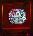
Thanks everyone for the help so far. I now have the scope connected in X Y mode direct to the B&K 415 and get a signal, see the below image. Further I have the direct probe connecting the B&K 415 to the Video detector (test point C1). The issue now is I get no feedback from the TV, whether connected to the TV or not I get the same curve on the scope.
Do I still use the Zenith service manual directions? I did try to connect the RF-IF-Video output and feed it into test point G as per the service manual but no change. Could something be wrong with the B&K 415? 
|
|
#10
11-24-2023, 11:35 PM
|
||||
|
||||
|
Very curious.
That does not look like an X-Y mode display. What it looks like is possibly the signal that should be going to the X axis (the left to right sweep) is showing on the Y axis,while the scope is still using its internal x axis (time) sweep. Also, do you have adjustable AGC bias connected from the B&K to the appropriate point in the receiver? The Zenith manual will tell you where to connect it.
|
| Audiokarma |
|
#12
11-25-2023, 11:53 PM
|
||||
|
||||
|
Quote:
jr
|
|
#13
11-26-2023, 08:45 PM
|
|||
|
|||
|
The problems were operator error, Jr was correct, I had never noticed the the very last time division setting was for X Y. With the scope maybe(?) now setup correct I am ready to go.
Note the first section of the scope output seems to be dead, regardless of the scope setting or the sweep settings. The first pic is while measuring the TV, the second pic is just from the B&K 415 and TV not connected:    On to the alignment, step 1 - 41.25 Trap Alignment:
Turns out I don't have the the right adjustment stick, mine is either worn or undersized, a 3/32 allen wrench fits perfect which is just under 0.1", I have order a plastic adjustment stick and will report back soon. Edit: adjustments sticks arrived, no adjustment was needed for L4.    
Last edited by bhegges; 12-02-2023 at 09:28 PM.
|
|
#15
11-26-2023, 09:45 PM
|
||||
|
||||
|
Looks like you've got it!
The offset you show with a question mark is the pulse that you saw before the sawtooth when you were accidentally not in XY mode. If needing the horizontal position set to max left is annoying, you can try switching to AC coupling on channel 1 (X). You can watch to see if the waveform shape changes. If it does, it's still OK to use it even if the *shape* doesn't look exactly like the Zenith manual. The important thing is the relative amplitude (vertical) at each marker, which will be good as long as channel 2 (Y) is DC coupled. The Zenith manual should tell you what percent of peak each marker frequency should be.
|
| Audiokarma |
 |
|
|


 Linear Mode

