
|
|
|
#31
 05-19-2012, 09:22 PM
|
||||
|
||||
|
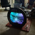
Thanks. It's far from finished... picture is still a little fuzzy and the screen needs to be degaussed. I'm kinda afraid to turn on the degaussing coil here in the living room... I need to first move all my reel-to-reel and VHS tapes to the other side of the room. I might just use my soldering gun to try to demag the screen. I used to have good luck with that before I got a coil.
I think it will be far better once I get the tuner cleaned up really good. I haven't changed the caps in the color section yet.... that can be for another day. Also, the horizontal is a little touchy. I think there's still two caps too be changed under the chassis in that department. The sound is really good. No buzz or static. I am curious about one thing... why is it my photos do not show up as tumbnails in my posts?
__________________
Charlie Trahan He who dies with the most toys still dies. 
|
|
#32
05-19-2012, 09:26 PM
|
||||
|
||||
|
Market Basket is a locally owned grocery chain to this area. They're celebrating 51 years right now. My younger siblings and I all worked there when we were in high school and college. I worked there 8 years before I started going to sea.
__________________
Charlie Trahan He who dies with the most toys still dies.
|
|
#33
05-27-2012, 01:54 PM
|
||||
|
||||
|
It's been a few days since I last played with this. Last night, I pretty much finished up (or at least as far as I'm going to take it at this point).
The tuner from the CTC11 is doing okay... but like Phil described his, this one, too, is kinda funky. I found that the best picture response shows up when I get the channel selector between channels 3 & 4. It really is kinda sloppy. I can't change the channel and come back without having to doing a major re-adjust of the fine tuner. But, until I can do something with the original tuner, this will have to do. The picture is a little grainy... not too bad. Tried repacing the nuvistor... no change. HV is set on 23KV. Tried to adjust the current in the horz section... was reading about 210ma. When I tried adjusting the coil to bring it down a bit, I found it was frozen in place and wouldn't budge. Damn! Typical. After trying to work it loose for some time, I finally gave up in fear or breaking the damn thing. I ran the set for some time and monitored the current. Stayed solid at 210. About an hour later, I felt the flyback and found it to only be slightly warm... about what you'd expect from it operating. I guess it will be okay... probably been that way for years. Does anyone have any tricks for loosening frozen coils without breaking them? I'd still like to get that current down just a little if possible. I never touched the convergence board. I felt it was acceptable as is. There are a couple of areas that look a tad off, but not so much that it bothered me. Perhaps later, I will touch up convergence if I go back in to swap out the tuner for the original. Something I found interesting... the place where the "stereo speaker" input is located... this chassis instead has a red screen control there. My other CTC9 actually has the speaker input. The back of the cabinet labels that spot as stereo speaker, and it lead me to think someone removed that input jack and stuck that red screen control there. However, when you look at it from the inside, it does appear to look like a factory job and not an add-on from some shop. Another question for thought... the red background control... why even have it??? In the set-up instructions, it clearly states to turn it fully counter-clockwise and leave it there... do not adjust. Even at the end of the instructions, it again says to leave it alone. Why have it if it's not to be adjusted? If i remember correctly, the later chassis did not have a red background control. As mentioned earlier, the CRT was replaced during the mid-late 60's. I noticed that the label has an "HR" prefix on the 21FBP. I wonder what the HR stands for? I don't think I've seen the HR before on any others. High resolution???  Yeah, I kinda doubt that. Yeah, I kinda doubt that. 
__________________
Charlie Trahan He who dies with the most toys still dies.
|
|
#34
05-27-2012, 04:44 PM
|
||||
|
||||
|
RE: cathode current
If the slug is frozen, put a hairdrier on it till it frees up. Then you should be able to adjust it faily easily. It's usually old wax that gets into them, so once you break it loose it should be OK. I was able to get cathode current on my CTC-9 down to 180ma, pretty low as it turns out. It's a careful balancing act between drive, horizontal tuning and the HV control. They all interact with each other, so play with it til you can't get it any lower. If you can keep it reliably below 200ma, the set will play for days without getting warm.
__________________
Evolution... 
|
|
#35
05-27-2012, 05:23 PM
|
|||
|
|||
|
Could the HR prefix mean Hi-Lite remanufactured?
|
| Audiokarma |
|
#36
05-27-2012, 07:33 PM
|
||||
|
||||
|
I will try the hair dryer next time I pull out the chassis. Certainly can't be any worse than the heat that gets generated in that cabinet!!
 The HR... I was always under the impression that Hi-Lite tubes were not rebuilds. Even if the tube was an actual rebuild that started out as a Hi-Lite, the old Hi-lite labels would have been removed during the rebuild process.
__________________
Charlie Trahan He who dies with the most toys still dies.
|
|
#38
06-01-2012, 06:21 PM
|
||||
|
||||
|
B+ Surge
It's pretty common that older sets with surge supression resistors (or thermistors) are found to have the component burned out, broken, or bypassed. This CTC9 was no exception. Someone had twisted the leads together like twisting the tie on a loaf of bread. I'm pretty sure I'm stressing those filters everytime I turn the set on.
I'm assuming that the auto-degaussing circuit in the newer sets also serves as surge supressor for the B+. With that being said, would it be acceptable to use a degaussing resistor in a CTC9 for the B+ surge supressor? I have a small handfull of these resistors for the degauss circuit... was thinking about plugging one of those in on my 9.
__________________
Charlie Trahan He who dies with the most toys still dies.
|
|
#39
06-01-2012, 07:21 PM
|
||||
|
||||
|
Would depend on if it has similar characteristics to the B+ device. However, since you don't have one in there now, won't hurt to try one & monitor how B+ comes up on startup.
__________________
Reece Perfection is hard to reach with a screwdriver.
|
|
#40
06-02-2012, 12:06 AM
|
||||
|
||||
|
Quote:
__________________
Chris Quote from another forum: "(Antique TV collecting) always seemed to me to be a fringe hobby that only weirdos did."
|
| Audiokarma |
|
#41
06-02-2012, 06:13 AM
|
||||
|
||||
|
Oh, yeah, that makes sense: the degaussing coil comes on strong and then fades away. My bad. I was thinking along the lines of a CL-90 inrush current limiter and similar ones that give a soft start and then their resistance goes down to just a few ohms as they warm.
__________________
Reece Perfection is hard to reach with a screwdriver.
|
|
#42
06-02-2012, 10:16 AM
|
||||
|
||||
|
Ah-haaa.... guess it's a good thing I asked!
 I'll check with Ralph's here in Beaumont and see if they have what I need. If not, i'll order the part online.
__________________
Charlie Trahan He who dies with the most toys still dies.
|
|
#43
06-02-2012, 01:07 PM
|
||||
|
||||
|
Quote:
Remove the channel selector knob. If you're lucky, you'll see a circular set of holes in the front of the tuner body. Using a strong flashlight, look inside and you'll see that for the current channel, the adjuster screw is exposed, deep inside. Turning the screw with a l-o-n-g skinny screwdriver should allow you to center the tuning for that channel. Changing to the next channel exposes that channel's adjuster. Note: I don't know if it's true for this set, but for some TVs you're supposed to adjust the oscillators in a definite order, for example, starting at channel 13 and working down to 2. I adjusted all of my channels in 13-2 order. Caution: if you unscrew the adjuster way, way too far, it may come out. On one of my sets, one of the adjuster screws was found hanging loose, halfway out of its hole. The Sams manual should have a procedure for doing this, likely with an oscilloscope. I used a Sencore VA62A that can output a test signal to any channel, adjusting each oscillator "by ear and eye" for best reception on each channel. An agile modulator like the B-T AM60-550B can also output to all channels. If you're not equipped to do the Full Monte procedure for all channels, it can't hurt to try tweaking the one or two that you use the most. However, if they're low channels and the procedure requires a high-to-low adjustment, perhaps that would be less successful than adjusting all of them, starting with highest. Regards, Phil Nelson Phil's Old Radios http://antiqueradio.org/index.html
|
|
#44
06-02-2012, 01:55 PM
|
|||
|
|||
|
Quote:
 but the circular set of holes applies to a wafer type tuner wherein all the adjuster screws are exposed, not just the one for the current channel. but the circular set of holes applies to a wafer type tuner wherein all the adjuster screws are exposed, not just the one for the current channel. By contrast, a turret tuner has just one adjustment hole so that changing to the next channel exposes only that channel's adjuster. Quote:
Quote:
|
|
#45
06-02-2012, 02:06 PM
|
||||
|
||||
|
The tuner in my CTC-11 is a (cheap) wafer type. I would LOVE to have one of those sturdy turret tuners, instead.
Phil Nelson 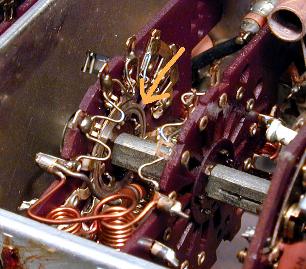
Last edited by Phil Nelson; 06-02-2012 at 02:09 PM.
|
| Audiokarma |
 |
| Thread Tools | |
| Display Modes | |
|
|


 Linear Mode

