
|
|
|
#121
 09-21-2018, 10:23 PM
|
||||
|
||||
|
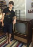
And we now have color and a decent picture! Went ahead and just aligned everything yesterday and today. Chroma and If are now aligned and the picture is pretty damn good. Dynamic convergence is an absolute nightmare on this one though so ill have to spend a few hours trying to sort that out tomorrow. I'll post more pictures after I do some touch ups of the basic setup.
__________________
 Admiral C322C2 Regent (Restoring) RCA CTC-7 Pensbury (Restored) RCA CTC-5 Westcott (Restored) CRA CTC--4 Director 21 (Restoring) 
|
|
#122
09-22-2018, 12:15 AM
|
||||
|
||||
|
Nice work.
__________________
Tom C. Zenith: The quality stays in EVEN after the name falls off! What I want. --> http://www.videokarma.org/showpost.p...62&postcount=4
|
|
#123
09-23-2018, 07:00 PM
|
||||
|
||||
|
I have been having trouble getting the chroma to stay in sync. Sometimes when the set is turned on, the chroma is working but then 15 minutes later the frequency goes off and the chroma dies leaving me with a black and white picture. And sometimes the set turns on with no chroma but then after 10 minutes im able to bring it back by adjusting the reactance coil. I have already tried replacing tubes to no effect and the resistors in the oscillator circuit seem to be fine with none grossly out of tolerance. Ill post a picture of the oscillator circuit and see if any has any ideas on what to check.
Oh and one thing that I think may be causing this is the fact that the -6v bias needed on pin 1 of the 6al5 and part of the color killer circuit drifts slowly. The chroma has been aligned so im not worried about improper alignment being an issue.
__________________
Admiral C322C2 Regent (Restoring) RCA CTC-7 Pensbury (Restored) RCA CTC-5 Westcott (Restored) CRA CTC--4 Director 21 (Restoring)
|
|
#124
09-23-2018, 07:36 PM
|
|||
|
|||
|
R178 12 meg could be drifting with heat. These high megaohm resistors are notorious for drifting.
|
|
#125
09-23-2018, 08:54 PM
|
||||
|
||||
|
Also check R179 10 meg going to 295 volts.
If I read the schematic correctly, pin 1 of the 6AL5 is the phase detector output, and the voltage *should* vary somewhat to keep the oscillator in sync as other circuit components drift. This is the voltage you monitor when adjusting the oscillator frequency, so if it varies after adjustment it means either that the oscillator frequency is drifting or some other input connected to the oscillator control is drifting, or the oscillator control itself is drifting, and causing the detector output to compensate and keep lock. When the drift is too big, the phase detector reaches its output limit, and the oscillator continues to go off frequency and out of lock. Once the circuit is out of lock, the output of the detector becomes a beat note (AC waveform) with less DC control voltage (average offset), so checking the DC when the oscillator is not locked doesn't tell you much.
|
| Audiokarma |
|
#126
09-24-2018, 06:39 PM
|
||||
|
||||
|
Replacing those resistors seems to have no effect. I wonder if the actual coil is drifting?
__________________
Admiral C322C2 Regent (Restoring) RCA CTC-7 Pensbury (Restored) RCA CTC-5 Westcott (Restored) CRA CTC--4 Director 21 (Restoring)
|
|
#127
09-24-2018, 09:36 PM
|
||||
|
||||
|
Have you tried replacing the 6U8 oscillator/control tube?
Also note C141, 2.0 pf NPO and C146, 82 pf NPO are both critical to frequency stability, which is why the temperature coefficient is specified. I would suspect these components before the coils, I think. Also C136, C145, C142, and C143 are supposed to be 10 or 100 times too big to affect the oscillator frequency, so I would check if they are in nominal range or not.
|
|
#129
10-07-2018, 06:35 PM
|
||||
|
||||
|
I have made a few advancements in the past week which I will discuss later. But first I need an answer on whether the cathode current I am getting is safe. Im getting 176 ma after dipping the horizontal linearity coil. Is this Ok for a 6cb5 and more importantly my fly back?
__________________
Admiral C322C2 Regent (Restoring) RCA CTC-7 Pensbury (Restored) RCA CTC-5 Westcott (Restored) CRA CTC--4 Director 21 (Restoring)
|
|
#130
10-07-2018, 06:54 PM
|
||||
|
||||
|
If it were a CTC-12/15/16, I'd say that is an excellent dip current...at the very least I'd imagine it is decent. You can only make that system so efficient with tubes and still have it work. If anyone knows the figure by all means correct me.
A good rule of thumb is temperature after 10, 30 min and 3 hour run times. If it is just a pinch warm holding it immediately after power off, but not very warm/ hot it is.probably fine.
__________________
Tom C. Zenith: The quality stays in EVEN after the name falls off! What I want. --> http://www.videokarma.org/showpost.p...62&postcount=4
|
| Audiokarma |
|
#131
10-09-2018, 07:18 PM
|
||||
|
||||
|
Was able to get it down to 170 with adjusting the drive. I feel a bit better now about it. Ill let it run for a while and see how hot the fly gets.
__________________
Admiral C322C2 Regent (Restoring) RCA CTC-7 Pensbury (Restored) RCA CTC-5 Westcott (Restored) CRA CTC--4 Director 21 (Restoring)
|
|
#132
11-12-2018, 03:57 PM
|
||||
|
||||
|
OK im in need of some help here with the color phase alignment. I have already completed the sync setup so im not worried about that. The scope steps of this procedure are very confusing and im not really sure what im looking for in the wave forms. Particularly steps 2 and 5-8. Can someone here tell me what im looking for when making those adjustments on the scope? I really want to get this project wrapped up before Christmas so any help is greatly appreciated!
__________________
Admiral C322C2 Regent (Restoring) RCA CTC-7 Pensbury (Restored) RCA CTC-5 Westcott (Restored) CRA CTC--4 Director 21 (Restoring)
|
|
#133
11-12-2018, 09:39 PM
|
||||
|
||||
|
Scope adjustments:
Step 2: you are adjusting the 3.58 MHz trap for minimum dot pattern on the screen, which will be seen as minimum "fuzz" or line thickness on the scope. (Scope sweep set to horizontal rate) Steps 6 and 7: you are adjusting the B-Y demodulator to have null ouput on R-Y and the R-Y demodulator to have null output on B-Y. If you don't have the specified bar generator, you can use a gated rainbow pattern and null out the appropriate bar. Set scope to horizontal rate. To adjust B-Y demod, one peak of the waveform should be on the burst and the opposite peak 6 bars later. The midpoint bar (third after the burst) should be nulled, that is, halfway between the peaks, and equal to the black background between bars. The red (R-Y) drive should have opposite polarity peaks on bar #3 and #9 and null on burst and bar#6. The blue (B-Y) drive should have opposite peaks on burst and bar#6 and null on #3 and #9. Last edited by old_tv_nut; 11-12-2018 at 10:07 PM.
|
|
#134
11-12-2018, 10:05 PM
|
||||
|
||||
|
These waveforms are from a Zenith, but the lower ones of each pair are essentially the same as you expect on any set with a gated rainbow signal
|
|
#135
11-13-2018, 06:40 PM
|
||||
|
||||
|
It also would have helped if I used the correct color bar pattern. I was just using a ntsc pattern which isnt right. But I dont have a generator that will produce that type of bar pattern. I dont know if my lcg 400 will make those bars or not.
__________________
Admiral C322C2 Regent (Restoring) RCA CTC-7 Pensbury (Restored) RCA CTC-5 Westcott (Restored) CRA CTC--4 Director 21 (Restoring)
|
| Audiokarma |
 |
|
|


 Linear Mode

