
|
|
|
#31
 12-14-2016, 01:27 PM
|
|||
|
|||
|
Pardon my waveforms
I had my eyeballs in upside down.
I've had good luck with video op amps like the MAX405. I got free samples but they may be hard to find these days. The only problem with video op amps is they require a bipolar supply and you might have trouble getting that in a tube set but solid state sets are usually no problem.
__________________


|
|
#32
12-14-2016, 06:19 PM
|
||||
|
||||
|
My issue currently is that I have too much gain with this circuit. How can I reduce the amount of gain at the output?
BTW: I am injecting at a tube grid, pin 1 on VT-6A below. 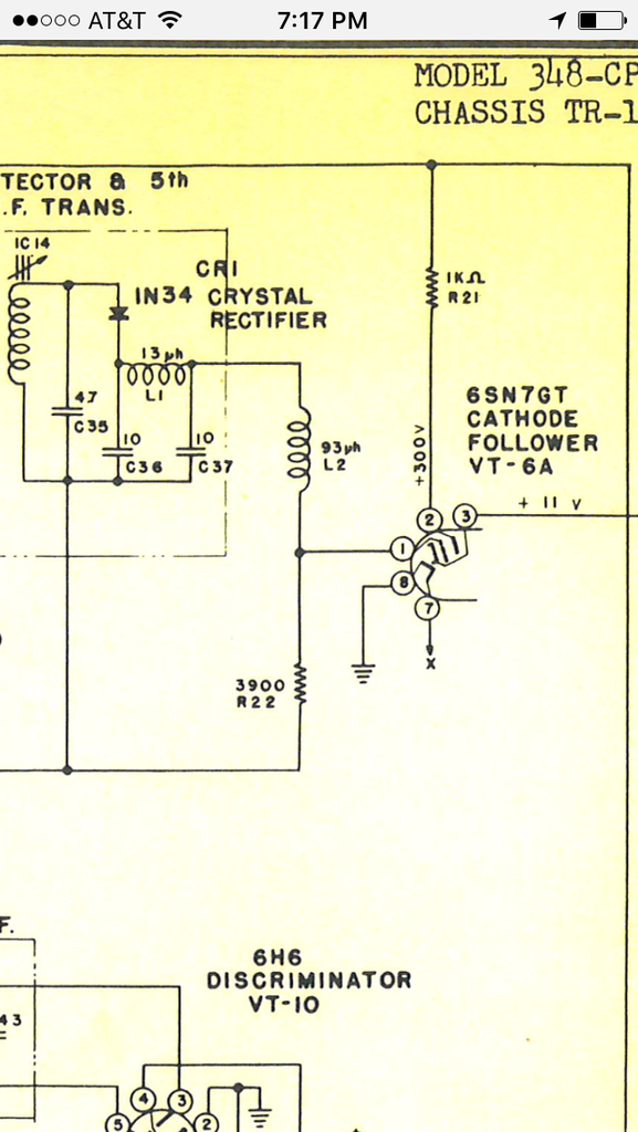
__________________
John
|
|
#33
12-14-2016, 06:28 PM
|
||||
|
||||
|
Quote:
You could use 2 resistors wired in a voltage divider configuration (or the adjustable version of it commonly known as a POTentiometer) at the circuit input or output.
__________________
Tom C. Zenith: The quality stays in EVEN after the name falls off! What I want. --> http://www.videokarma.org/showpost.p...62&postcount=4
|
|
#34
12-14-2016, 06:52 PM
|
||||
|
||||
|
Quote:
 . What are the implications of adding resistance at the input vs output? . What are the implications of adding resistance at the input vs output?
__________________
John
|
|
#35
12-14-2016, 07:58 PM
|
||||
|
||||
|
Looking at the circuit again...
At the input if you put it before the blocking cap you may have impedance mismatch with your coax, if you put it after you will change transistor bias (which could resort in distortion), if you ad another DC blocking cap you may create a RC filter network (and would have to make sure it does not attenuate in the video pass-band). Feeding the output of the coupling/blocking cap into your pot/divider seems the most logical idea to me.
__________________
Tom C. Zenith: The quality stays in EVEN after the name falls off! What I want. --> http://www.videokarma.org/showpost.p...62&postcount=4
|
| Audiokarma |
|
#36
12-14-2016, 07:59 PM
|
||||
|
||||
|
If you have a potentiometer of value somewhere between 2k and 2.5k, you could substitute it for the 2.2k collector resistor. If you have a 5k potentiometer, you could parallel it with a 4.7k resistor and substitute the parallel combination for the 2.2k collector resistor.
Connect the output capacitor to the potentiometer wiper instead of the transistor collector.
|
|
#37
12-19-2016, 02:28 PM
|
|||
|
|||
|
Here are two video input adapters
The left one is for a Heathkit GR2000 and the right one is for an RCA CTC74. Both are built on 2x2 circuit boards and attached to the IF module with silicone rubber. They output to the first video amplifier.
The Heathkit adapter uses a MAX405 video op amp and the RCA uses a compound pair of transistors. Both are configured for a 6X output. Both work equally well. The choice for the video op amp was made because a bipolar supply was available in the Heathkit but this was not the case in the RCA. The cable exiting the adapters is the video input cable.
__________________
|
|
#38
12-22-2016, 07:41 PM
|
||||
|
||||
|
Quote:
OK, I remade the inverter following this schematic, with the exception of the 2.2 K resistor which is a potentiometer/parallel resistor of the same overall value. The output is greatly improved. One problem I am having is what looks to be vertical interference as you can see from this video. The vertical bars look like a horizontal problem in the television, but it's in the video itself. When I adjust the potentiometer you can see at some point the vertical bars change direction. Thoughts? https://www.youtube.com/watch?v=G7Xc...&feature=share
__________________
John
|
|
#39
12-22-2016, 08:23 PM
|
||||
|
||||
|
Hard to guess without more details of the circuit and investigation with an oscilloscope. One possibility is that the point where you are injecting needs a DC-restored signal in order for sync separation to work properly. So, you are seeing AC hum (perhaps a separate problem) plus you are seeing it un-synced until you have enough amplitude. Then when it is synced, maybe it's OK, but maybe not. You didn't stop adjusting at a good point or make the video long enough to tell what's going on. You need to adjust for an intermediate level where it syncs and see if it remains in sync or loses it depending on the picture content. If it's unstable with video content, it probably means DC restoration is needed.
Please publish more of the TV's circuit and where you are connecting the amp, if you can.
|
|
#40
12-23-2016, 07:22 AM
|
||||
|
||||
|
I should have been more specific on what I was doing in the video. The beginning of the video is showing a blank screen because I have paused the source. The vertical lines are way easier to see when there's nothing on the screen. I am adjusting the potentiometer in one direction and at second 3 you can see the vertical bars stop and start moving in the other direction. Then at about second 6 I start moving the potentiometer in the other direction and you can see the vertical bars stop and move back in the original direction. Then at second 11 I played the source video again so you can see the problem isn't vertical hold in the set itself. The set lost vertical sync as you can see, but the bars are "in front" of that. I continue to adjust the potentiometer with the source material playing.
I'll shoot another video and give a play by play voice over of what I am doing. Here's more of the TV circuit. I am injecting at pin 1 of VT-6A below and have removed the output from the detector that was going there. 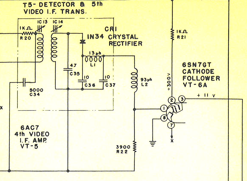 Pin 3 of VT-6A goes to pin 6 of the seven pin plug P7. 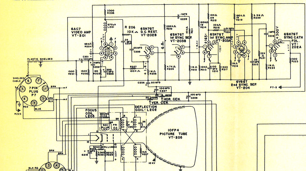
__________________
John
|
| Audiokarma |
|
#41
12-23-2016, 09:55 AM
|
||||
|
||||
|
OK, this shows a DC restorer before the sync separator, So you should not need one in your input circuit, at least not for sync.
I suggest the following to try to chase one problem at a time: 1) Adjust the gain of the transistor amplifier to get normal contrast. 2) Leave it there. 3) Chase the hum bars. To make sure I'm following right, does the cathode of VT6a (pin 3) go to pin #6 of plug P7 and hence to R201?
|
|
#42
12-23-2016, 10:06 AM
|
||||
|
||||
|
OOPS - I see the DC restorer is not feeding the sync separator. But since it is AC coupled to start with, you do not need one in your circuit for that purpose.
Got my wires crossed and I now see the DC restorer is for the video - this also means you don't need one in your amplifier circuit.
|
|
#43
12-23-2016, 10:10 AM
|
||||
|
||||
|
By the way, where are you getting the 12 V supply for the amplifier? Any hum, noise or instability of the supply will transfer directly to the output on the collector.
|
|
#44
12-23-2016, 10:48 AM
|
||||
|
||||
|
Quote:
Quote:
Quote:
__________________
John
|
|
#45
12-23-2016, 01:17 PM
|
|||
|
|||
|
Why not use a battery? 9V would probably run it OK, and drain would be minimal. Give it an on/off switch.
(Hum bars are the horizontal dark shadings in the raster due to 60 or 120 Hz ripple (hum).
|
| Audiokarma |
 |
|
|


 Linear Mode

