
|
|
|
#1
 04-14-2017, 08:43 PM
|
||||
|
||||
|
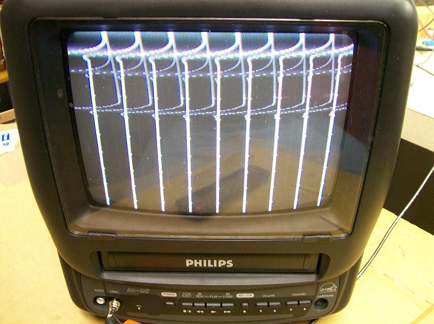
Heathkit IO-101 Vectorscope/Pattern Generator Insanity .
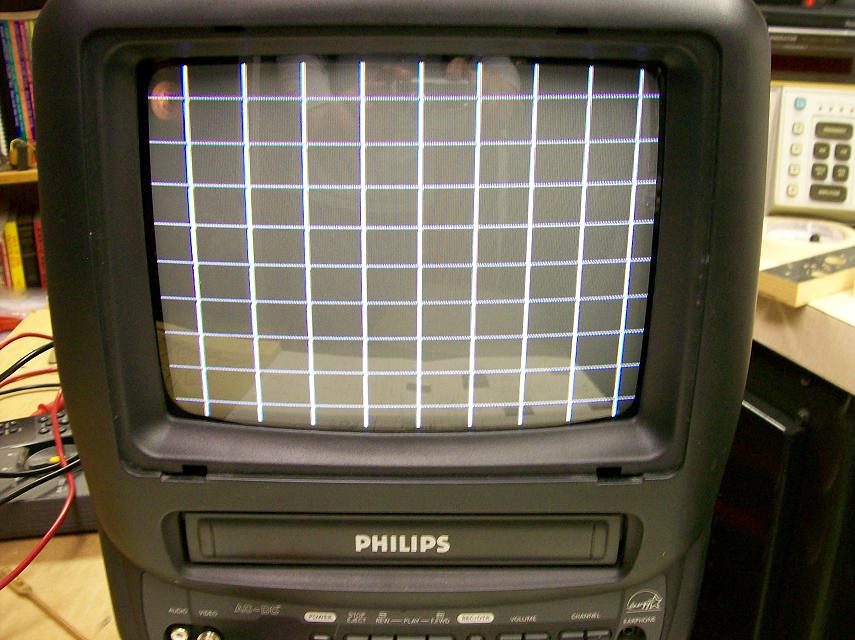
A nice man gave me this unit a couple weeks back and it's about driving me crazy. I can't for the life of me figure out what's wrong with the composite video signal that's causing the wave at the top of the picture. I have the manual and all the video waveforms look good on my scope. It shows nearly the same symptom on both vintage and modern TV's, and regardless of whether it's connected to the tuner or composite video in on the newer set. This uses the same pattern generator circuit as in the Heath stand alone IG-28. If you fast forward about 11 minutes into this youtube video you'll see this fellows generator exhibits very nearly the same behavior as mine. In fact when I hooked my Admiral 20Z1 chassis up to mine it looks nearly identical to his. For some reason the vertical bars bend to the left on the Admiral. https://www.youtube.com/watch?v=3G1_2XyXfFs
Last edited by Kevin Kuehn; 10-21-2017 at 08:47 PM. 
|
|
#2
04-14-2017, 08:55 PM
|
||||
|
||||
|
I've got the same unit. Reseat the ICs and maybe clean their sockets. Heath socketed all their ICs back then and the connections turn to crap with age. I've had two of the generator only variant of this and one was near dead till I re-seated the ICs....I had a heath scope of this vintage as my first...It had so many intermittents from those sockets that I gave up and sold it many years ago. The gens tend to be more stable.
__________________
Tom C. Zenith: The quality stays in EVEN after the name falls off! What I want. --> http://www.videokarma.org/showpost.p...62&postcount=4
|
|
#3
04-15-2017, 01:19 AM
|
||||
|
||||
|
Tom,
I did replace those funky individual pin IC sockets with some decent AMP sockets. I've verified all the divide by flip flops and gates are doing their math correctly. This thing uses the ancient Motorola MC700P series RTL family IC's. I'll try to post some scope screen shots of the composite and maybe someone sharper than I will notice something I'm overlooking.
|
|
#4
04-15-2017, 01:40 PM
|
||||
|
||||
|
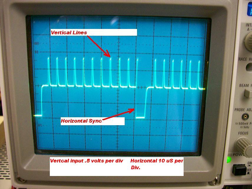
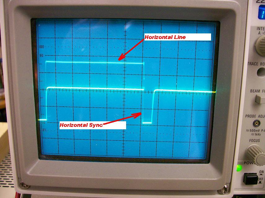
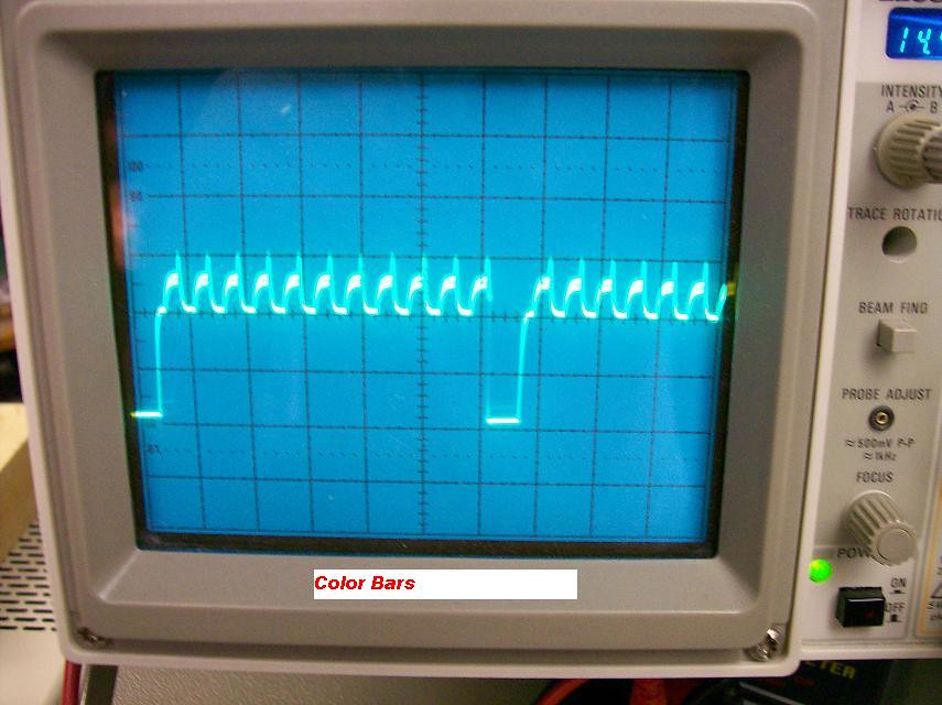
Here are pictures of the pattern composite wave forms. Vertical scope input is .5 volts per division.
Last edited by Kevin Kuehn; 10-21-2017 at 08:52 PM.
|
|
#5
04-15-2017, 05:52 PM
|
||||
|
||||
|
I was staring at my scope screen pictures and it finally dawned on me that the vertical sync pulse was about 1500 uS long. Duh! So I tried adjusting the vertical blanking pot and it has zero effect on the width of the sync pulse.
Last edited by Kevin Kuehn; 10-21-2017 at 08:53 PM.
|
| Audiokarma |
|
#6
04-15-2017, 08:05 PM
|
||||
|
||||
|
That was it. The vertical sync pulse was so long it was blanking too far into the beginning of next frame. All it needed was a 1.5k resistor from ground to the vert sync input of the sync mixer gate, so now the vertical blanking width control works as expected. The way it was, the gate input couldn't recognize the change in pulse width(RC differentiator) because it had no DC reference. Apparently that was an inherent design flaw. Now I have to wonder if Heathkit at some point implemented a fix for that small oversight.
Last edited by Kevin Kuehn; 10-21-2017 at 08:55 PM.
|
|
#7
04-15-2017, 11:56 PM
|
||||
|
||||
|
Before you fixed the problem I was going to say that the horizontal sync pulses look a little too wide. Maybe your fix changed that also.
|
|
#8
04-16-2017, 12:32 AM
|
||||
|
||||
|
Quote:
Last edited by Kevin Kuehn; 10-21-2017 at 08:57 PM.
|
|
#9
05-11-2017, 12:56 PM
|
||||
|
||||
|
I've had one of these for a long time. If I remember correctly, mine does the same thing. I replaced all the IC's and IC sockets. I'll pull it out. Maybe you just got the answer on fixing these critters!
|
|
#10
05-12-2017, 09:56 AM
|
||||
|
||||
|
I've got mine open here. Digital IC's are not my forte', I admit. Could you tell me from what junction of two parts you put the resistor to ground.
|
| Audiokarma |
|
#11
05-12-2017, 10:43 AM
|
||||
|
||||
|
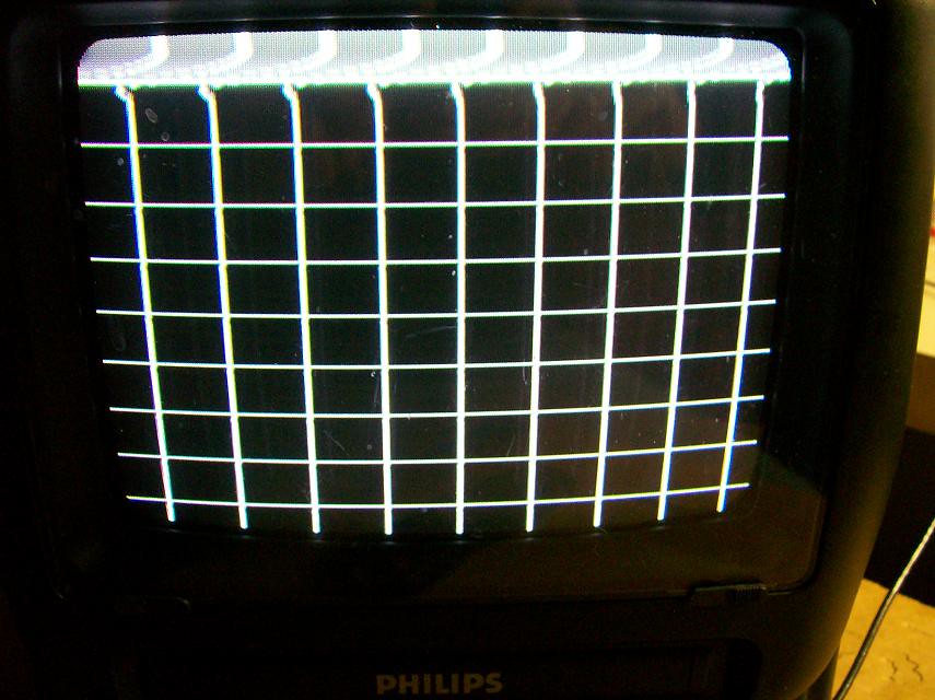
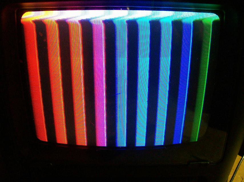
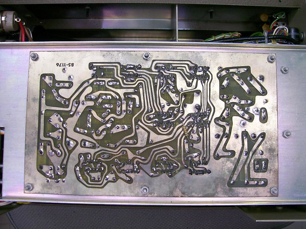
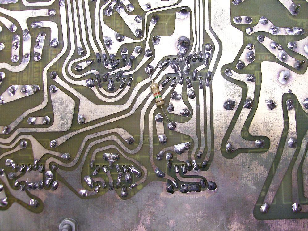
Here's a couple pictures of where I located the 1.5K on the back side of the circuit board. It's between pin 4(ground) and pin 10(input to G1 gate which is IC 9 in the manual). You will need to adjust the Vertical Blanking Width pot(R35) in order to get the best line pattern at the top of the picture. Basically you will be adjusting the width of the vertical blanking pulse, which determines where at the top of the screen the horizontal scan begins. When that pulse is too wide you see the vertical blanking pulse turn off transistion, which is what causes the wiggle in the vertical lines. Hope that makes sense. Let us know how it works out.
Last edited by Kevin Kuehn; 10-21-2017 at 09:00 PM.
|
|
#12
05-12-2017, 12:03 PM
|
||||
|
||||
|
Mighty big THANKS!!! I fought this unit for days and finally gave up! It sat in my upstairs room for a while now!
I wonder how many other people have given up on one of these because it just didn't make sense! Again, Thanks!!!!!!!
|
|
#13
05-12-2017, 01:32 PM
|
||||
|
||||
|
Cool. And you're very welcome. It's always good to know that the fix works on more than only my unit.

|
|
#14
05-12-2017, 01:41 PM
|
||||
|
||||
|
Your Sony has way better vertical linearity than my Philips.
|
|
#15
05-12-2017, 02:26 PM
|
||||
|
||||
|
That Sony was saved from the street! It had the remote taped to the top. I like it because it is a mono unit with video in. It works great with my SL-2000 Beta portable.
I always got a chuckle out of Sony's cabinet colors! Again, thanks!
|
| Audiokarma |
 |
| Thread Tools | |
| Display Modes | |
|
|


 Linear Mode

