
|
|
|
#136
 01-22-2013, 08:56 PM
|
|||
|
|||
|
i check those two resistors in the plate circuit R603 and R604.
R603 is coded as an 82k which was on on the CTC-5 but shown as a 100k on the N chassis. I checked it out of the circuit and it had drifted up to about 94k so I left it alone. the R604 which is coded as a 39k tested at 60k. Its 10% banded so I went ahead and replaced it with a 39k (tested at 41k) from my stash of old carbon comp resistors. there was also a 1000pf cap that was from the junction of those two resistors to ground, If it leaked it would really mess things up, so I pulled it out and tested it. It tested perfect with no leakage so I put it back in. It was one of the red dominos, but I don't like to replace parts that check out perfect. The only other caps in on the H board that were not replaced were a couple 82 pfs that were in the AFC circuit. As I was having no issues with sync I left them alone. I really need to reinstall the chassis and see where I am just need to make some room in the shop as I don't want to work on it out in the garage. 
|
|
#137
01-22-2013, 09:38 PM
|
||||
|
||||
|
Quote:
|
|
#138
01-23-2013, 08:24 PM
|
|||
|
|||
|
will do.
I noticed in the RCA service manuals the CTC-5N had the 100k listed with 120k and 150k alternates. My plan is to try it as is (with the new 39k) and then try a 120k for the R603 (vs the 94k reading 82k resistor that is in there now. all this time I have been saying I have the N chassis, I just double checked, its a AA chassis.
|
|
#139
01-23-2013, 08:35 PM
|
||||
|
||||
|
Quote:
I think the problem is the back flyback HV supply design with limited beam current in this set. It would be nice to be told whether or not the CTC5 picture is as dim as other color sets of the same vintage.
|
|
#140
01-24-2013, 11:14 AM
|
||||
|
||||
|
CTC-4 is definitely brighter, but it also has a stiff 25kv anode supply. The later sets all had better horizontal sections as well, not as good as a 4 or 21-CT-55, but the 5 is the only odd one out of the whole early color RCA line with respect to HV generation. I still would like to one day sub a different anode supply into a 5, to see if more HV would make it perform as well as the others.
__________________
Evolution... 
|
| Audiokarma |
|
#141
01-25-2013, 08:07 AM
|
||||
|
||||
|
I think a few minor modifications to the sweep circuitry may be all that is required. I do not like the static convergence DC supply coming from the horizontal output cathode. Tying the cathode to ground and providing a separate DC supply might help. I expect there are other issues with the design as well.
I agree that the CTC5 seems the odd one out.
|
|
#142
01-25-2013, 10:49 AM
|
||||
|
||||
|
Quote:
Quote:
__________________
Evolution...
|
|
#143
01-25-2013, 11:19 PM
|
||||
|
||||
|
Quote:
I am suggesting tying the cathode to ground. This will in effect copy the later chassis' CTC7 onwards. I am curious if it is not the reactances in the cathode circuit which reduces the flyback pulse amplitude and makes the HV supply soggy? As for the DC supply for the static convergence, I was was thinking of constructing a separate regulated DC supply. The DC would be derived from the filament supply. A suggested diagram is attached. Certainly, simply ignoring the static convergence and simply grounding the Horizontal Output Tube cathode right at the socket would test the HV supply and I will be game to try it when next I pull the chassis.
|
|
#144
01-26-2013, 10:48 AM
|
||||
|
||||
|
Huh, I thought they pulled waveforms from there as well. It's been a while since I've been inside my Wingate, and I don't have it near me to play with it since I moved or I'd try it myself. Seems to me it would change the operating point of the output tube by a little bit, but probably not much. It would have the effect of driving the stage harder, since lowering the cathode voltage to ground would turn it 'on' more. But since the same thing can be achieved by the drive pot mod I already did (which accomplished nothing), I suspect the result will not be more HV output. Curiously though, I noticed that the 5 is not as prone to getting drive lines as the other chassis are. All these things are what leads me to believe that the transformer itself it what they changed, since it all leads back to that one part of the circuit.
__________________
Evolution...
|
|
#145
01-26-2013, 02:26 PM
|
||||
|
||||
|
I would expect the HO tube bias measured with respect to ground to rise by 5 or 6 volts when the cathode is grounded by virtue that the bias is derived by grid rectification. Hence the total bias is dependent upon the drive amplitude.
My thought is the added reactance to the cathode circuit (5ufd cap and wiring) may hinder the ability for th HO tube to be turned off at the end of forward scan. This would reduce the pulse height and inrease the effective series impedance of the HV supply. This is only my thought and I'd next like to explore. Last edited by Penthode; 01-26-2013 at 02:29 PM.
|
| Audiokarma |
|
#146
01-28-2013, 10:06 PM
|
|||
|
|||
|
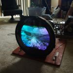
getting there, I brought it in the shop, put the chassis back in and started setting it up (I had swapped in a replacement CRT, so I knew it would require a full setup)
In the process of adj the yoke for level I got bit pretty good. seems the outside of the CRT cover is not grounded very well. Perhaps thats just the way it is with these 21AXP22. I will confirm that all my grounding straps are in place on the CRT cover hold down AND the connection the the chassis is good. From what I can see the only connection to the chassis is a pressure connection from tabs on the front of the CRT mount that press into the chassis on the front. I had a heck of a green neck shadow that I could not seem to correct without upsetting the purity. I never got the purity perfect anyway, I could get the red blob right in the cener with nice blue and green blobs around it, but when I moved the yoke forward I could not get a pure red screen, the bottom was the problem. I have not yet futz with the screen magnets nor tried degaussing (My 1st 21AXP22 set) so I will have to figure out how to adj the perimeter magnets so they are retracted and give it a proper degausse. This set is def a bit trickier than the later roundies I have worked on. I need to get a handle on this hot yoke first. I did not try and measure it but the metal plate is def sparking up when grounded.
|
|
#147
01-28-2013, 10:24 PM
|
|||
|
|||
|
shoving the chassis up tight against the front of the set seems to have solved the grounding issue of the yoke, need to look into that a bit better. Maybe scuff up the chassis and the springs that make the contact and make sure all is clean. I am a little bit surprised there is not ground strap directly to the chassis.
|
|
#148
01-29-2013, 10:52 AM
|
|||
|
|||
|
I was not able to get the bezel out of the way, I can get the top out (the 3 spring clips that hold it in) and the side are not retained but the bottom is not budging. I looked at an old bezel that was loose and I see two holes that I assume fit over pegs on the bottom but can not say for sure.
Wingate owners please comment on how to remove.
|
|
#149
01-29-2013, 01:44 PM
|
|||
|
|||
|
while fussing with it I decided to check the voltage at the horz out fuse, was around 12v IIRC, now its more like 7.5 right on the money per the schematic
 during the intial setup I checked the blue screen purity (after getting the red as good as I could) the green was good but the blue was TERRIBLE.. I tried turning up the drive which helped but it was not just weak but more blue/green. during a prelime setup of the center convergence I noticed the blue was way out, so I tweeked the blue lateraly, bingo blue not only converged but overall was much brighter. seems the blue lateral must have been causing the really bad purity also. all this is just me messing about, I know I need to do a proper setup using the instructions which are a lot more complicated than what I have seen in other later roundies with later convergence boards.
|
|
#150
01-29-2013, 05:52 PM
|
||||
|
||||
|
Quote:
Remove the pencil box knobs. Remove the pencil box. This wll reveal, at the top of the opening, two spring loaded metal inserts that hold the bottom of the bezel in place. Take a small flat blade screwdriver and place into the insert and push down. You can do one at a time. This will release the insert from the bezel. Reverse the process when replacing the bezel. -Steve D.
__________________
Please visit my CT-100, CTC-5, vintage color tv site: http://www.wtv-zone.com/Stevetek/
|
| Audiokarma |
 |
| Thread Tools | |
| Display Modes | |
|
|


 Linear Mode

