
|
|
|
#106
 01-04-2009, 09:14 PM
|
||||
|
||||
|
Quote:
However, thanks for the suggestion, and please continue to make suggestions if you think of anything. The best thing may be to make new, longer straps. 
|
|
#107
01-04-2009, 09:26 PM
|
||||
|
||||
|
Quote:
I am definitely saving all pieces I remove! If I could adapt the metal shield to hold the CRT, it would be more like the RCA adapter kit, but it has no mounting tabs, and as I said above, it is exactly the same size as the CRT "well," so it won't fit either inside or outside. Cutting notches and flaring it would probably work, but I'd still have the problem of attaching some sort of mounting tabs. Still noodling, but maybe the best bet is to take the mounting ring to a metal shop and have them duplicate the straps, but 4 inches longer and with ends angled perpendicular to the face. Edit - I really appreciate everyone trying to come up with some ideas.
|
|
#108
01-11-2009, 04:51 PM
|
||||
|
||||
|
having a (tight) fit!
I poked around the hardware store, and ended up making a hinged bracket out of two brass L-brackets. I used these for the bottom mounts that interfere with the chassis.
For the top mounts, i reduced the padding and moved it towards the CRT face, as was suggested earlier. I removed the edge field-compensation assemblies, aslo as suggested earlier. You can see that the hinged bracket fits quite well on one side, but since the holes as supplied are offset, doesn't clear the existing boss for the field-compensator on the other side, so is cocked a bit. I tried to bend one of the ground contact sprihgs that grounds the pencil box to the chassis and also stops full forward placement, and broke it. I think one will be enough, though. You can see that I am very close to making contact between the CRT and couple of tubes. I also included a picture of the alignment on the right side (viewed from rear) chassis mounting. You can see it's barely clearing. The left side does not clear with the tubes just about to hit the CRT. However, the controls seem to extend enough through the pencil box with this position. Plan: 1) give it a rest for today 2a) drill/enlarge mounting holes in cabinet; 2b) arrange some sort of stop to prevent the chassis sliding too far forward 3) cut down the tube shield that is almost touching the CRT
|
|
#109
01-11-2009, 04:54 PM
|
||||
|
||||
|
tight fit part 2
here's the pic of the tube near-interference
|
|
#110
01-11-2009, 06:45 PM
|
||||
|
||||
|
Looks good Wayne, getting much closer. I would try not to drill the cabinet at all as much as possible. Can you bolt it in where the controls will just fit? That tube getting close shouldn't hurt anything. I would just cut the shield if it don't fit.
__________________
My TV page and YouTube channel Kyocera R-661, Yamaha RX-V2200 National Panasonic SA-5800 Sansui 1000a, 1000, SAX-200, 5050, 9090DB, 881, SR-636, SC-3000, AT-20 Pioneer SX-939, ER-420, SM-B201 Motorola SK77W-2Z tube console McIntosh MC2205, C26 
|
| Audiokarma |
|
#111
01-11-2009, 07:37 PM
|
||||
|
||||
|
The problem is that the left side holes don't line up at all (I think they're off by just one diameter), and the unshielded vert tube on the left cannot go further forward. I don't think enlarging the holes in the plywood base and shimming to keep the chassis from going forward the extra 1/4 inch is a big deal. I just want to be able to move the set without having the chassis slide around and hit tubes against the CRT or straps. As you can see, the mounting holes had some slop anyway, which was OK before, but needs to be tightened up now. As long as the control knobs fit, the chassis could stay in the new position even if I got an original CRT to install at a later date.
|
|
#112
01-12-2009, 11:43 AM
|
||||
|
||||
|
Ahhh, I see what you mean. I am looking forward to seeing her up and running. This has been a long project with many obstacles to overcome. Should be very worth it in the end though. Good luck Wayne!
__________________
My TV page and YouTube channel Kyocera R-661, Yamaha RX-V2200 National Panasonic SA-5800 Sansui 1000a, 1000, SAX-200, 5050, 9090DB, 881, SR-636, SC-3000, AT-20 Pioneer SX-939, ER-420, SM-B201 Motorola SK77W-2Z tube console McIntosh MC2205, C26
|
|
#113
01-17-2009, 03:14 PM
|
||||
|
||||
|
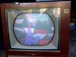
Fianlly - first light
Today I took a look at the mounting and decided maybe the chassis would just barely fit - and it does.
Here are the pix of the first light on the rebuilt 21FBP22. #'s P1170014s, -018s, -019s at power on with no adjustment whatsoever. The other three (next post) after some adjustment.
|
|
#114
01-17-2009, 03:25 PM
|
||||
|
||||
|
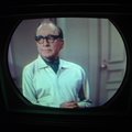
Three pix after some adjustment.
Problems: Insufficient width (plenty of height) HV regulation isn't working very well - size changes somewhat with contrast, can cause pic to bloom at max contrast - need to jmeasure Focus at one end of range Poor H lin - should I tweak drive waveform? Blue H dynamic convergence out of range /not doing much R/G V dynamic covergence going to end of controls [need to investigate position of neck hardware] Purity not perfect, but will work on that after Horiz problems are fixed 60 Hz hum in audio Some 60 Hz hum in horiz (size or phase?) Forgot how much V hold, V size and V lin interact on these old sets!
|
|
#115
01-17-2009, 03:34 PM
|
||||
|
||||
|
Way to go Wayne! That set is coming along nicely. You might try replacing the HV rectifier, focus rectifier, HV regulator, and damper tubes and see if this improves your HV performance. The only reliable way to check the HV tubes is in circuit. Thanks for the photos, and keep us posted!
__________________
John Folsom
|
| Audiokarma |
|
#116
01-17-2009, 04:28 PM
|
||||
|
||||
|
I did check all the tubes in this set on a tube tester, and replaced those that measured weak. But testing in circuit is a good idea now that I have everything running.
By the way, I need to rig up a ground lead for the CRT - I'm just using a clip lead to the mounting strap, which has a dag contact spring. Hypothetically, there is a ground path from the dag to the strap to the mounting bolts to an existing ground wire, to a bowed contact spring in the front of the cabinet (the one remaining after I broke one -see previous post) to the chassis. However, the chassis contact spring is a bit rusty, and the contact is poor to non-existent. Need some sort of clips that could clip onto the mounting strap on one end and the chassis on the other. **Any hints about the width and H linearity would be greatly appreciated. I do have it on a variac and line meter, tried raising the voltage a bit, but that is not the fix.
|
|
#117
01-18-2009, 05:25 PM
|
||||
|
||||
|
Turned it on and let it run for most of the afternoon to see what would drift or smoke.
Vertical height, linearity, and hold all drift for the first 30 minutes. Horizontally, it started out with a bit more width, but within a few minutes was back to the same narrow picture as yesterday. Focus is still at one end. Played with off-air signals (amplified rabbit ears, admittedly suboptimum for this location), found tremendous variation from station to station, especially in color level. Of course, everthing interacts, but the fine tuning is especially a nuisance. Tuning to the supposed optimum point (just below sound interference in the picture) reduces the sound volume. So, the sound detector must be sensitive to the intercarrier amplitude. Found that the hum/buzz in the audio depends on video content, so this is looking more and more like a complete IF alignment. Checked out the UHF (won't have any after Feb 17), found it will not make snow through the whole frequency range, so there may be some AGC or other problem. Went through the background and G2 (screen) adjustments. Could not get the DC reading I'm supposed to on red G-K as a starting point (115 V max, instead of 130). It does make a B&W picture, though for all settings of brightness and contrast. I think the B+ is OK (by measuring video output voltages), but I didn't find an easily accessible point to measure with the chassis in the cabinet. Blue dynamic convergence controls seem dead. Red and Green seem to be lacking range. Adjusting convergence coils position didn't seem to make much difference. Played with purity and improved it, but now horiz centering is at one end and would like to go further. I will measure the HV at some point, but I found that the convenient lead on my HV meter is just too big in diameter to go in the connector in the HV compartment, and can't be squeezed small enough. Have to rig something. Need to revisit the AGC setting, turning it down a bit from max improved the color transient response, but makes the picture dim at max contrast. Now I'm musing whether I will need to replace a bunch of resistors in addition to the recapping. Well, at least no smoke so far -- As my relatives used to ask me, "When do you think they will perfect color TV?"
|
|
#118
01-18-2009, 09:50 PM
|
||||
|
||||
|
Not a totally unfamiliar pile of issues! What can I offer? I actually think HV is pretty easy to measure on these, at least with the probe I have, since the whole metal base of the HV rectifier socket is at second anode voltage. Just stab it in there somewhere close.
I've had trouble with some convergence controls not seeming to make much difference. I haven't dug that far. I haven't had width problems; I have the control set at the highest of the 3 settings. Before I buttoned everything up last time I adjusted the vert & horiz lin for a very nice circle in the middle of the screen but now it's all distorted again. That didn't last long. Things on these sets seem to vary a lot with voltage, time or ??? I have also noticed, clearly, the difference in color & brightness from station to station. I know this was a selling point in later color sets, so I guess this was seen as a major shortcoming to some folks. You can wear that tint control out while channel surfing! This is proof that not all the improvements in color tv were in consistency at the station. Even today these sets struggle. That's okay...gives them "character"! For the grounding strap, can you do something with a long, thin spring? Lots of sets used something like that. Hardware store should have a selection.
__________________
Bryan Last edited by bgadow; 01-18-2009 at 09:52 PM. Reason: addition
|
|
#119
01-18-2009, 10:12 PM
|
||||
|
||||
|
Thanks for the info, Bryan.
For the ground, I was thinking along the lines of "speednut" u-clips on the ends of a wire. But I have to think about a flat spring mounted on the chassis - might work and be simpler! Now for a little begging: Would anyone have a blue lateral magnet laying around? [HA!] The one that came with this set is partially broken (I think). The magnet part was held in place with electrical tape and is really loose (seems about to fall out), making it tough to adjust and leave adjusted without moving it. Or maybe they're all like that, in which case, never mind! If no one has a spare, I'd still like to see what a good one looks like.
|
|
#120
01-19-2009, 11:00 AM
|
|||
|
|||
|
[QUOTE=old_tv_nut;2419985]Thanks for the info, Bryan.
For the ground, I was thinking along the lines of "speednut" u-clips on the ends of a wire. But I have to think about a flat spring mounted on the chassis - might work and be simpler! QUOTE] Where did you get that picture of all the different tinnerman nuts? Looks like a good supplier we all should be made aware of.
|
| Audiokarma |
 |
|
|


 Linear Mode

