Videokarma.org

Go Back   Videokarma.org TV - Video - Vintage Television & Radio Forums > Early B&W and Projection TV

We appreciate your help

in keeping this site going.
Reply
 
Thread Tools Display Modes
  #76  
Old 04-05-2023, 10:00 PM
Chris K Chris K is offline
VideoKarma Member
 
Join Date: Jun 2022
Posts: 664
Got it. I received my usb/laptop oscilloscope this evening and I’ll trace it out tomorrow night. Thanks Bob
Reply With Quote
  #77  
Old 04-06-2023, 06:59 AM
Chris K Chris K is offline
VideoKarma Member
 
Join Date: Jun 2022
Posts: 664
Quote:
Originally Posted by bandersen View Post
No, if you have sound but absolutely no vide, I seriously doubt it's the detector. A scope should give you the answer in a few minutes. Start at the detector and go through each stage to the CRT. At some point the signal will disappear and that will be the problem point. I suspect either something is open or shorted.
Morning Bob...do you mean move forward in the circuit between the detector and the CRT or check the entire RF/IF string? Timmy has commented it's possible to have sound but no video due to problems prior to the detector but others have commented if there's sound, your video information is getting lost somewhere between the detector and the CRT cathode. There's not much between the detector and the CRT...a couple of coils and capacitors and all have tested good. I have a resistance on the video amp pin 5 that's spot on by the Sams. I've checked physical wiring continuity from the 0.05uf cap to the halfway plugged in CRT pin 2 and that's all there as is continuity through the 2 small coils after the detector. I've tried a different 7JP4 and have the same raster/no video result. Totally stumped but I will look for the actual signal with a scope next.
Reply With Quote
  #78  
Old 04-06-2023, 10:23 AM
bandersen's Avatar
bandersen bandersen is offline
RCA 741PCS
 
Join Date: Mar 2009
Location: Chicago, IL
Posts: 8,106
Between the detector and the CRT.
Check the signal at the grid of the video amp.
Check the signal at the plate of the video amp.
Check the signal at the cathode of the CRT.

Note that the sound is picked off the screen of the 6AU6 video amp while the video comes off the plate. So I'm thinking it's possible that circuit is screwed up in some way that allows the signal off the screen to be OK, but not from the plate.
__________________
Here are my Vintage Radio & TV YouTube Channel and Photo Gallery
Reply With Quote
  #79  
Old 04-06-2023, 11:03 AM
Chris K Chris K is offline
VideoKarma Member
 
Join Date: Jun 2022
Posts: 664
Understood. Thank you very much!
Reply With Quote
  #80  
Old 04-07-2023, 08:17 PM
Chris K Chris K is offline
VideoKarma Member
 
Join Date: Jun 2022
Posts: 664
Scope Pics

Keeping in mind, I just got this thing and my skills with it are very, VERY limited, I took pictures of the waveforms of the signals going into the video amp pin1, and out the video amp pin 5. The scope has an auto trigger and an auto adjustment feature that creates the best display parameters. First in pin 1 input from the detector. The second is pin 5 video output. Am I doing this trace correct so far? I've never looked at a video signal on an oscilloscope before. I'm feeding an RF modulated video into it and I have sound but no image information on the CRT...just a raster.
Attached Images
File Type: jpeg image0 (21).jpeg (120.9 KB, 18 views)
File Type: jpeg image1 (7).jpeg (130.0 KB, 18 views)
Reply With Quote
Audiokarma
  #81  
Old 04-07-2023, 09:25 PM
bandersen's Avatar
bandersen bandersen is offline
RCA 741PCS
 
Join Date: Mar 2009
Location: Chicago, IL
Posts: 8,106
No. Look at the frequency. It's 60Hz. You're just seeing noise from the AC line.
Amplitude is pretty big too. What do you have the ground of your scope connected to?


Get that frequency dialed in to more like 45kHz or higher so you can see the horizontal sync pulses.

It should look something like this.
__________________
Here are my Vintage Radio & TV YouTube Channel and Photo Gallery

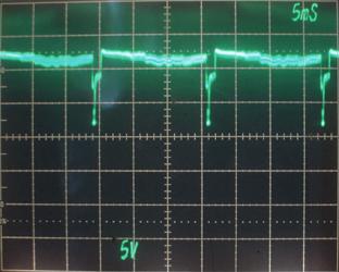
Last edited by bandersen; 04-07-2023 at 09:30 PM.
Reply With Quote
  #82  
Old 04-07-2023, 09:38 PM
Chris K Chris K is offline
VideoKarma Member
 
Join Date: Jun 2022
Posts: 664
Ground is connected to the chassis. I thought I was seeing AC when I saw that. The 60Hz pulse is what is going into the amp pin 1 from the detector.
Reply With Quote
  #83  
Old 04-07-2023, 09:41 PM
bandersen's Avatar
bandersen bandersen is offline
RCA 741PCS
 
Join Date: Mar 2009
Location: Chicago, IL
Posts: 8,106
No, the chassis is not ground - it's floating. Connect your scope to B-. Same place the negative leads of your electrolytics caps are going.
__________________
Here are my Vintage Radio & TV YouTube Channel and Photo Gallery
Reply With Quote
  #84  
Old 04-07-2023, 10:14 PM
bandersen's Avatar
bandersen bandersen is offline
RCA 741PCS
 
Join Date: Mar 2009
Location: Chicago, IL
Posts: 8,106
and make sure you have the TV running on an isolation transformer!
__________________
Here are my Vintage Radio & TV YouTube Channel and Photo Gallery
Reply With Quote
  #85  
Old 04-08-2023, 06:05 PM
Chris K Chris K is offline
VideoKarma Member
 
Join Date: Jun 2022
Posts: 664
I don't have one...just a Variac but I ordered one so I'll keep away until it's safe!
Reply With Quote
Audiokarma
  #86  
Old 04-08-2023, 06:40 PM
bandersen's Avatar
bandersen bandersen is offline
RCA 741PCS
 
Join Date: Mar 2009
Location: Chicago, IL
Posts: 8,106
Yikes! Remember B- connects directly to one side of the AC plug. If you connect that to ground on your scope - POW!
__________________
Here are my Vintage Radio & TV YouTube Channel and Photo Gallery
Reply With Quote
  #87  
Old 04-08-2023, 08:55 PM
Chris K Chris K is offline
VideoKarma Member
 
Join Date: Jun 2022
Posts: 664
Quote:
Originally Posted by bandersen View Post
Yikes! Remember B- connects directly to one side of the AC plug. If you connect that to ground on your scope - POW!
Scope is OK. I did try it (), grounding it to B-, but the scope still works ok on my calibration generator. That's my issue with understanding parts of this hobby and being out to lunch with other things. I'm a science guy...a biology professor and researcher, but there are things about electronics where I have no idea what I'm doing. Feel pretty stupid at times working on these things...but I just learned B- connects directly to one side of the AC line!!!!!
Reply With Quote
  #88  
Old 04-08-2023, 10:52 PM
Electronic M's Avatar
Electronic M Electronic M is offline
M is for Memory
 
Join Date: Jan 2011
Location: Pewaukee/Delafield Wi
Posts: 14,820
You should also check continuity of the ground lead of your scope probe....The positive path can be OK at the same time the ground is open and the probe will still work on the scopes internal calibrator because they share an internal ground, but connect it to a working TV chassis and you'll get hum and weird behavior from the open ground...Ask me how I know!
__________________
Tom C.

Zenith: The quality stays in EVEN after the name falls off!
What I want. --> http://www.videokarma.org/showpost.p...62&postcount=4
Reply With Quote
  #89  
Old 04-08-2023, 11:43 PM
Chris K Chris K is offline
VideoKarma Member
 
Join Date: Jun 2022
Posts: 664
I used an external frequency generator atom
Reply With Quote
  #90  
Old 04-08-2023, 11:44 PM
Chris K Chris K is offline
VideoKarma Member
 
Join Date: Jun 2022
Posts: 664
Tom. Not atom!!!!
Reply With Quote
Audiokarma
Reply


Posting Rules
You may not post new threads
You may not post replies
You may not post attachments
You may not edit your posts

BB code is On
Smilies are On
[IMG] code is On
HTML code is Off

Forum Jump


All times are GMT -5. The time now is 10:12 PM.


Powered by vBulletin® Version 3.8.4
Copyright ©2000 - 2024, Jelsoft Enterprises Ltd.
©Copyright 2012 VideoKarma.org, All rights reserved.