
|
|
|
#31
 03-16-2017, 11:58 AM
|
||||
|
||||
|
Quote:
 RCA did succumb to cost cutting, and how! RCA did succumb to cost cutting, and how!

|
|
#32
03-16-2017, 01:25 PM
|
||||
|
||||
|
I could advise you to check the IF transformers with an ohmmeter, you might disturb their pins while recapping. If even one of the windings gets opened, you loose the signal completely.
BTW, I've never seen a bad interstage mica.
__________________
To understand a bygone era, you should use things from it Last edited by Gleb; 03-16-2017 at 01:56 PM.
|
|
#33
03-16-2017, 11:13 PM
|
||||
|
||||
|
Quote:
The loss of the video IF stage means that about 1MHz of video response was lost. I suppose the loss of picture detail was worth the cost saving. There was a couple of RCA B&W models with four VIF stages in 1953 but I believe they were gone in 1954. I believe the best RCA B&W sets were built between 1948 and 1952. (The cheapened kcs47 chassis is an exception). The kcs66 (Million Proof) sets were the epitome: they employed intercarrier sound, four video IF stages, DC video coupling and keyed AGC. They went downhill from here.
|
|
#34
03-17-2017, 10:45 AM
|
||||
|
||||
|
Assuming the wiring to each stage is correct and the tubes are conducting and the tube dc voltages are present, then evaluating the IF alignment can begin. Replacing the capacitors and altering the wiring dressing, will dramatically affect the staggered tuning. There is a lot of gain in the VIF strip and if the tuning of two stages coincide, the strip will likely oscillate resulting in a total loss of picture.
To determine if the VIF is oscillating, measure the dc voltage across the detector load resistor with no signal input. There should be no DC (less than one volt DC). You need to test this first. Reducing the contrast control will increase the bias on the first stages (there is no AGC in the ts630). If the IF is indeed oscillating, you will reach a point the dc across the detector load will dramatically drop. It is important that the IF strip is not in oscillation before proceeding. Next, rough alignment is first achieved by injecting a signal stage by stage and tuning each of the staggered stages to what is recommended. Then as each stage is tune to its recommended frequency, you would use the sweep generator to review the combined stagger tuned response. Follow the RCA published data for the ts630 and it will say essentially the same thing.
|
|
#35
03-17-2017, 06:53 PM
|
||||
|
||||
|
Quote:
|
| Audiokarma |
|
#36
03-17-2017, 07:56 PM
|
||||
|
||||
|
Quote:
I once saw a Colby and it had a very good picture. Have you put a resolution chart up to check the frequency response?
|
|
#37
03-17-2017, 08:10 PM
|
||||
|
||||
|
Quote:
|
|
#40
05-26-2017, 08:54 AM
|
||||
|
||||
|
Quote:
The riveted in "candohm" resistor (R186) can be replaced with a pair of chassis mount 10W power resistors (Ohmite HS10 series or similar). I use 6.8K and 100 ohms, as the closest standard values, with no problems. You will need to drill new mounting holes, after removing the original resistor. Last edited by N2IXK; 05-26-2017 at 09:00 AM.
|
| Audiokarma |
|
#41
05-26-2017, 10:01 AM
|
||||
|
||||
|
That's what I did too. Notice the sliders are near the extremes to get 1360 and 230.
Next time around though I think I'll use a 1.5K and 250 ohm fixed and parallel them with resistors to get the exact value. Fixed are half the cost of the adjustable ones. 15K in parallel with the 1.5K 2.7K in parallel with the 250 2W should be enough. Most of the current will be running through the big power resistor. 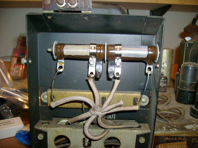
|
|
#44
05-26-2017, 12:59 PM
|
|||
|
|||
|
What did you do for the R209? The 5300 segment is open. The connection is on the middle of the three pronges at the top. Is that 5300 + 500 for 5800 ohms since the three top pronges are for the 500 ohms and the connection is on the middle pronge. What value is it? 5300 or 5800 ? And any suggestions for best place to get it.
Thanks Bandersen for the pix. I try do nice work too. What's the difference between the 8TS30, not the 6TS30. The schematics look the same. Last edited by Montman; 05-26-2017 at 02:20 PM.
|
|
#45
05-26-2017, 01:38 PM
|
||||
|
||||
|
The 630TS has an electromagnetic ion trap; 8TS30 is PM. I think some of the 630TS sets have a field coil speaker; all of the 8TS30 sets, and most of the late production 630TS, should have a PM speaker.
|
| Audiokarma |
 |
|
|


 Linear Mode

