
|
|
|
#106
 06-19-2011, 10:09 AM
|
|||
|
|||
|
Quote:

|
|
#107
06-19-2011, 11:20 AM
|
||||
|
||||
|
Quote:
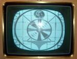
My CTC2 had been powered up for the first time yesterday since breaking down the RACS 15GP22 rebuild demo at ETF on May 1; since then it traveled over 1500 miles in the back of my Yaris, so I was very glad to see the HV still working (including the ozone if you were there seeing and smelling it operating at ETF!) and only the green channel not operational. Glad to have been able to inspect the proto chassis up close; still many, many questions to resolve. Nick and Bob found a socket for a crystal, but there's no positive indication that it is for 3.579595 mc. What a great opportunity we few had to participate in and witnesss such an historic event. Pete
__________________
Vacuum tubes are used in Wisconsin to help heat your house. New Web Site under developement ME http://AntiqueTvGuy.com Last edited by ohohyodafarted; 06-19-2011 at 11:24 AM.
|
|
#108
06-19-2011, 01:00 PM
|
||||
|
||||
|
First-Light 1952>>2011
Fantastic work Nick, Pete, and Bob! I'm really glad you guys were able to get to "First-Light 2011" in such a short period of time.
|
|
#109
06-19-2011, 02:09 PM
|
||||
|
||||
|
Quote:
__________________
Evolution... 
Last edited by miniman82; 06-19-2011 at 08:16 PM.
|
|
#110
06-19-2011, 02:23 PM
|
|||
|
|||
|
Wouldn't it be nice if you could lay hands on the engineering notes for your prototype? Delay line questions, burst frequency, convergence supply specifications, how and if high voltage is regulated, what tubes go where, the list seems endless.
It looks as if this thread could last a while. That's perfectly fine by me. 
|
| Audiokarma |
|
#111
06-19-2011, 02:56 PM
|
||||
|
||||
|
My guess is that all these questions will be answered by our color experts as Nick traces the circuits.
|
|
#112
06-19-2011, 03:21 PM
|
||||
|
||||
|
Yes, the schematic is the thing.
__________________
John Folsom
|
|
#113
06-19-2011, 04:32 PM
|
||||
|
||||
|
Posible CPA Set
To the Color Gang,
Nick and I have just had a wonderful 1 1/2 hours on the phone tracing his chassis circuits from the CRT grids back through the 6BL7 color crt drivers,and 6AS6 demodulators. We had discussed the evolution of NTSC standards, back through the Feb. 2, 1953 NTSC Field Test Specification, and further back to the initial definition of the NTSC field test standard published on November 26, 1951. See http://novia.net/~ereitan/NTSC_overview.html This November 26, 1951 standard used quadrature modulation of 1 MHz. B-Y and R-Y color difference signals, CPA (Color Phase Alteration), a 3.898125 MHz. subcarrier, and reference burst on a pedestal on the back porch of horizontal blanking. . In doing our tracing Nick discovered a transformer labeled "CPA". Our initial conclusion is that it is a chassis probably used during the CPA Field Testing during 1952. There were several manufacturers who built field test receivers during that period. We have yet found nothing to confirm that it was built by RCA or by any other manufacturer. The chassis may have been modified from CPA up to the later NTSC Feb. 2, 1953 standard. We will see. Further tracing of the circuit and documenting the circuits will be don. Ed Reitan
|
|
#114
06-19-2011, 04:35 PM
|
||||
|
||||
|
Very interesting indeed!
__________________
John Folsom
|
|
#115
06-19-2011, 04:52 PM
|
||||
|
||||
|
Thank you Ed for the revealing and informative conversation, the amount of information that the early color crowd is providing is astounding to say the least. The collective knowledge shared here cannot be found anywhere else on planet Earth, of that much I am certain and I am forever grateful!
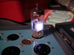
As Ed indicated, we started out following the wires though the various components connecting each stage to the previous one. I was poking around in an area that I had assumed would have something to do with demodulation, positioned in the circuit just prior to the 6BL7 grid driver tubes, and containing 6AS6 tubes. That's when I struck gold: Hidden under some passive components was a chassis stamp in black ink right under a tall transformer, which reads CPA. It's a pretty tall can, so I was curious what it had inside. Taking much care not to damage or disturb anything, I slowly removed the nuts holding it to the chassis and this is what's inside. It's only about half the total height of the can, and appears to be some sort of transformer. I cannot see any kind of slug in the center of it, so I'm assuming it's an air core non-adjustable type.
__________________
Evolution...
|
| Audiokarma |
|
#116
06-19-2011, 06:01 PM
|
||||
|
||||
|
Quote:
Pete
__________________
Vacuum tubes are used in Wisconsin to help heat your house. New Web Site under developement ME http://AntiqueTvGuy.com
|
|
#118
06-19-2011, 07:22 PM
|
||||
|
||||
|
Wow! This is all very fascinating, will be watching this thread with great interest...
__________________
Visit my Vintage TV & Radio Page - http://nzvintagetvradio.blogspot.com/ My YouTube Link - http://www.youtube.com/user/glenz1975?feature=mhsn
|
|
#119
06-19-2011, 07:26 PM
|
||||
|
||||
|
This get's more interesting by the day! Probably one of the most interesting things that's happened here yet.
The genesis of Color TV being uncovered before our eyes, it's one thing to read about field tests and demonstrations for the FCC, quite another thing to see the actual hardware rediscovered and brought to life. It's only been 60 years since this was being created but so much seems to have been lost. I suppose it's lucky there's as much written documentation as there is, I wish there was a few hundred hours of period Technicolor footage to go with it. They must have filmed some of their tests?? To go back in time with a HD Flip Camera hidden in my pocket.
|
 |
| Thread Tools | |
| Display Modes | |
|
|


 Linear Mode

