
|
|
|
#31
 02-03-2005, 03:15 AM
|
||||
|
||||
|
Quote:
http://bs.cyty.com/menschen/e-etzold...ig/type349.htm Quote:

|
|
#32
02-03-2005, 05:35 AM
|
|||
|
|||
|
Wow. Wow... That Grundig television is absolutely beautiful. I always have loved the styling of the Grundig sets, with the big slide-rule dial scale and large knobs, and the piano key switches. I'd never seen that in a television before, but I like it
 I've got a Grundig console hi-fi with a very similar tuning scale and layout, and I love it. It sounds wonderful on the phono, but the radio plays weak. I just need to get off my butt and replace the caps in the circuit... Can't complain though, I found the console on the side of the road, waiting for the garbage. Hard to believe someone would throw out something so beautiful, but I guess people would much rather have the cheap, Wal-Mart crap these days. I've got a Grundig console hi-fi with a very similar tuning scale and layout, and I love it. It sounds wonderful on the phono, but the radio plays weak. I just need to get off my butt and replace the caps in the circuit... Can't complain though, I found the console on the side of the road, waiting for the garbage. Hard to believe someone would throw out something so beautiful, but I guess people would much rather have the cheap, Wal-Mart crap these days. As for the styling of newer European sets, with the black band around the tube, from what I can tell, it's just that they mounted the tube such that the entire glass section sticks through the front, rather than cover up the edges with a bezel like the American sets. I actually kinda always thought that looked neat, at least on some of the 60's/70's B&W 12" sets. Never seen one in person, only in pictures, but since that sort of 12" plastic portable set is so common here, and they all have the same basic design, having the entire tube visable makes it look a little more interesting. Never been able to find one like it here though, something tells me I won't. Doubtful that anyone moving from Europe to the US would bother bringing along a cheap 12" black and white television, only to have it be totally incompatible with the US systems... -Ian
|
|
#33
02-03-2005, 06:26 AM
|
||||
|
||||
|
Quote:
Quote:
http://bs.cyty.com/stjakobi/unskirch...-Jakobiz74.jpg (this PAL tv set has a color *and* a tint control!) and the first Telefunken solid state portable (with a delta-crt): http://bs.cyty.com/menschen/e-etzold...inBetrieb2.JPG Grundig used the same crt-type. They didn't stick it through the cabinet but used a bezel: http://bs.cyty.com/menschen/e-etzold...2000TDvorn.jpg Not as beautiful as the elder models was the second Telefunken color tv: http://bs.cyty.com/menschen/e-etzold...inBetrieb2.JPG On the website of Marcel van Grinsvens TV-Museum you can see a lot of european sets (this is - in my opinion - one of the largest documentation of european early tv sets on the web, but the site is completely in dutch language. Marcel doesn't understand English, it's very difficult to communicate with him. But his website is worthy to visit: http://www.marcelstvmuseum.com/
|
|
#34
02-03-2005, 07:30 AM
|
|||
|
|||
|
A lot of really interesting sets at Marcel's museum, interesting how different trends in design evolve. I do rather like the look of the fully exposed CRT face, probably because it's so different. I've never seen an American TV like that. That second Telefunken color set is a very nice looking one, I like the clean lines and the balanced design. Another thing I've noticed is that it seems to be more popular in the european sets to have the controls mounted lower, and the speaker above them - exactly opposite most American televisons, where the controls are normally mounted closer to the top of the set. Another big difference in the apperance of the European sets is the lack of tuning knobs, something that persisted in the US until the 80's. Nearly every American TV from the 70's will have two knobs, one for VHF (Channels 1-13, and a position to select UHF) and one for UHF (14 - 83). My guess is that the European sets didn't have to worry about dealing with such a large number of channels, so pushbutton tuning was practical even without digital tuners. I'm not familliar with the TV system outside the US, I know that most of Europe uses PAL, and France uses SECAM, but I don't know about the channel allocation. Just, from looking at the sets, there are six pushbuttons on that Telefunken, so what, six channels?
Now, that's not to suggest that the US has more channels, we just have more channel numbers. To prevent overlapping transmitters in different areas, the stations are spread around the band a little. It's not uncommon to only be able to pick up three channels in an area, and a couple weak UHF stations. -Ian
|
|
#35
02-03-2005, 07:43 AM
|
||||
|
||||
|
Quote:
|
| Audiokarma |
|
#36
02-04-2005, 12:34 PM
|
||||
|
||||
|
Quote:
Parallel to L106 (horizontal tuning coil) there has to be a 0.15 capacitor (c114) according to the service manual. But only 0.1 were installed. Might it have an effect on the picture width?
|
|
#37
02-05-2005, 09:35 AM
|
|||
|
|||
|
Eckhard. Have the caps been replaced? I assume you did. I checked my manual and c114 shows a .01. One end connects to pin 3 of the 6cg7 the other end to ground. Check pin 3 on the 6cg7. The voltage should be around 10v. If it is, you should be ok. Check the horz drive voltage. Should be around -38v.to -40v on pins 4-5 on the 6cb5. If ok Turn the ac up to 110v. Set the width switch to the middle position and check the horz current. see what you get. I have mine set to 198 ma with the ac set to 114v. Another thing you should check is the high voltage regulator current The reading should be around 0.8 ma with the brightness turned all the way down.The high voltage to the crt should be around 22kv. You have to take the information you read in a manual with a grain of salt. Sometimes they make mistakes.{only human}Or rca did a production change. Voltage readings may be off by a couple volts. or you see parts that show a diffrent value. That is normal. I go by the value of the old part I am replacing.as long as it looks like the original part. Another thing, If you replace the caps in the power supply make sure the value of the replacement is the same as the original. If you go to high{80uf to 100uf} It may upset other sections of the chassis and can make the flyback run hot.{ Been there, Done it, Diden't like it.}
good luck ED
|
|
#38
02-07-2005, 04:28 AM
|
||||
|
||||
|
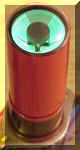
Caps already had been replaced (except for the color units) before I get the set. I have changed c114 to 0.1. Horizontal drive voltage is -20v on pin 5 on the 6CB5 (with 105 volts ac). The +385 v supply has only 317 volts (with 105 ac) and 365 volts with 114 volts ac. I measured crt heating voltage again, but now directly on pin 1 and 14 of the crt, it is 6.15v (with 114 ac). But I checked the focus control R129 and opened it. It had burned out inside, see photo. The focus control seems to be the true source of inconstant picture and arcings! I have renewed it. The picture now is sharp and clear with rich contrast and brightness. But there is still something to do to set the d.c. currents properly. Perhaps the 5U4 are weak because of the additional electrolytics for the canadian 25 cycle rectifying.
|
|
#39
02-07-2005, 07:57 AM
|
||||
|
||||
|
So Erick is gonna get his hands on an old color tv. Uhh. I want a one like taht too!
|
|
#40
02-07-2005, 08:00 AM
|
|||
|
|||
|
With the width control set at center and the ac at 114v. Do the sides of the picture fill the screen? What is the horz current reading at 114v ac? Check the high voltage to the crt, Is it around 22kv? Did you check the high voltage regulator current {6bk4}? When you are running the set on a lower ac voltage, The dc and heater readings will be a little low.That is normal. I am glad you are getting a good picture, Makes it worth all the work you are doing to the set. When you get the time, Replace the caps in the color section.{To avoid problems}
ED
|
| Audiokarma |
|
#41
02-07-2005, 03:17 PM
|
||||
|
||||
|
Sorry, but I have some simple (and silly?) questions. When I remove the chassis, I can't get it easily into working condition outside the set, because the cables (connection to the deflection jokes) are too short. The only possibility is to turn it around 180 ° and put it with the back half into the set. Do you have any tricks? Is there anything to hanging in the chassis while servicing in operating mode?
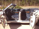
With 114 v ac and width control at center position, the sides of the picture fill the screen, see http://bs.cyty.com/menschen/e-etzold/1a.jpg For checking high voltage current and the other measures I need some help to put the chassis into a suitable service position. In the moment servicing is very pedantically.
|
|
#42
02-07-2005, 03:35 PM
|
|||
|
|||
|
I am currently working on two CTC-5s and have the same problem with the chassis. RCA produced a set of extension cables that allowed the chassis to be set on the top or side of the cabinet. It is possible to make a set of these but the hardest part is to find the connectors for the convergence plug. You probably could back the chassis into the cabinet but the anode lead may not be long enough to get into the high voltage cage.
Steve
|
|
#43
02-07-2005, 03:58 PM
|
||||
|
||||
|
Yagosaga- Awwww, man, that's a nice picture !!! You've done an EXCELLENT job...Congrats are in order. I was a bit resentful at first that one of these guys had left the country, but now that I see how you've treated it, the "love" & respect you obviously show towards it, I don't think it could be in better hands.... My hat's off to you, sir !! -Sandy G.
__________________
Benevolent Despot
|
|
#44
02-07-2005, 04:03 PM
|
||||
|
||||
|
Quote:
- An old tv serviceman here in Brunswick told me, when he was servicing these old color tv's in the 1950s and 1960s in the U.S., they fetch only the chassis from the owners, not the whole set, and hang it into the van. In the repair workshop they had a frame, where they hang the chassis in. At the workbench they had a crt with different adapters, so they could connect the chassis. Then they repaired it, and if one could find the failure within a specified time, he has to change with another serviceman. After repairing they brought back the chassis and put it into the set. (But I don't have a RCA workbench... ;-)
|
|
#45
02-07-2005, 04:18 PM
|
|||
|
|||
|
Wo ist Brunswick order ist das Braunschweig? Es tut mir leid mein deutsch is nicht gut aber ich werde Deutschland in Mai besuchen. I will send you a PM so others don't get upset over my poor use of German!
Bis dann, Steve
|
| Audiokarma |
 |
|
|


 Linear Mode

