
|
|
|
#1
 06-16-2009, 05:30 PM
|
|||
|
|||
|
Calling all CTC-5ers: How did you set your HV?
I'm kinda stumped: I've been going through the 1955-1966 RCA Field-Service Guide and of all the models from CTC-2B thru CTC-10 the only one that doesn't have an HV adjust is the CTC-5. The 1956 T6 Service Data is remarkably cryptic, basically saying to measure the current across fuse F104 (with fuse removed, I assume) and set it to something less than 220 ma while watching the HV with a high voltage probe to show a reading somewhere between 18 and 22 KV. RCA also suggested that the usual regulator (6BK4) cathode current be checked to set black to no less than 800 microamps using tuning or detuning of L106; the same coil you use to set the current at F104. This seems to be a rather indirect way of going about things. Wouldn't it make some sense to put in an HV adjust pot of say 500K along with a series fixed resistor of 1.5 meg in place of R125, a fixed 1.8 meg resistor (grid to ground path?)
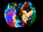
Another question: Why is it that of all the various RCA models which used the 21AXP22, the 5 seems to have the lowest HV? Are they trying to tell us something from the corporate grave? Also: Of much less significance than the above: Does someone out there have one of the Bakelite 45 degree high frequency speaker supports for the "Panoramic" tweeters in the Deluxe model CTC-5? Mine was delivered with one smashed and I need to replace it.... Thanks for your help! 
|
|
#3
06-16-2009, 07:35 PM
|
||||
|
||||
|
Hi: While I don't know for sure why RCA reduced the HV in the 5's, I suspect it was because the previous two chassis (CTC-2B, and CTC-4) applied 25KV to the 21AX, and produced a bleep-load of X-RAYS as a result. A friend came over with a radiac meter, and we measured approx. 4 milirems/hr at white screen on my CTC-4, which is a bit high, although I don't think there is too much danger unless one sits with their nose to the safety glass for a few months.
The CTC-7, and some subsequent chassis also had HV below 25KV, but a bit higher than the 5's , most likely because of the new all-glass 21CY producing fewer X-RAY's. The later leaded-glass CRT's allowed even higher HV, some around 40 KV. Others: Please comment! Kevin
__________________
stromberg6
|
|
#4
06-16-2009, 07:35 PM
|
||||
|
||||
|
My question was answered as I was typing.
 But now I have another, How can the 5 produce as bright a picture as other sets using the same CRT with lowered HV well below other sets. But now I have another, How can the 5 produce as bright a picture as other sets using the same CRT with lowered HV well below other sets.
__________________
My TV page and YouTube channel Kyocera R-661, Yamaha RX-V2200 National Panasonic SA-5800 Sansui 1000a, 1000, SAX-200, 5050, 9090DB, 881, SR-636, SC-3000, AT-20 Pioneer SX-939, ER-420, SM-B201 Motorola SK77W-2Z tube console McIntosh MC2205, C26 
Last edited by zenithfan1; 06-16-2009 at 07:39 PM.
|
|
#5
06-16-2009, 09:51 PM
|
||||
|
||||
|
With mine I got the currents where they should be but kept trying and trying to get the HV up. I had to settle for about 18kv. The picture looks nice, though, so I finally decided to stop worrying about it.
Side note: I fired the -5 up for the first time in a few months...I wanted to give it one more taste of analog Friday night. Darn-no raster, sounded like no HV. Too much trouble to pull it out right now. Had this happen once before and it was a cracked HO tube; hopefully it's something simple like that.
__________________
Bryan
|
| Audiokarma |
|
#6
06-17-2009, 02:20 AM
|
||||
|
||||
|
Quote:
Operate the set for one hour and touch the LOPT or measure the temperature. Is it hot? The temperature should not exceed 40°C. - Eckhard
|
 |
|
|


 Linear Mode

