
|
|
|
#47
 08-10-2017, 07:50 PM
|
||||
|
||||
|
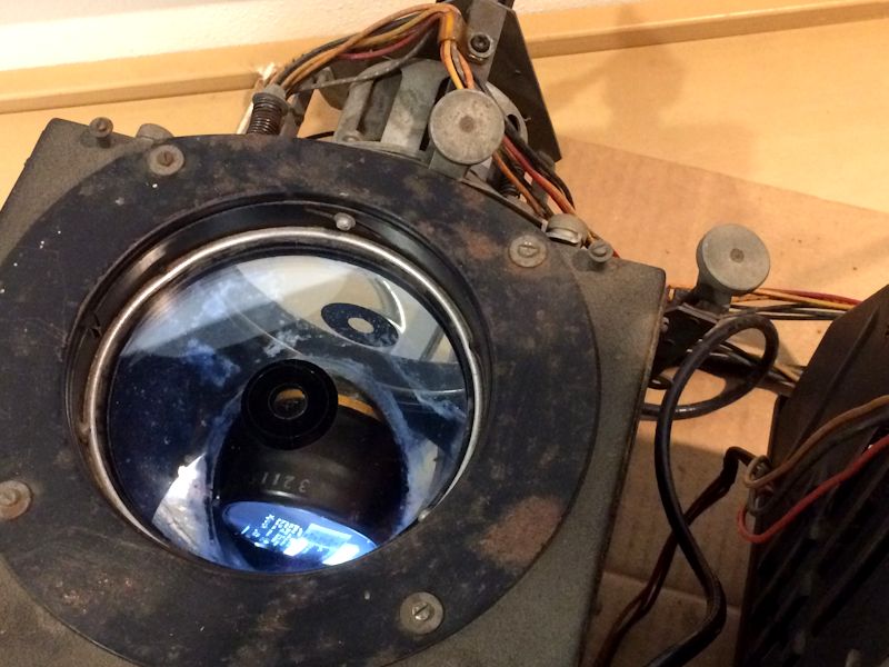
I pulled the chassis and opened the optical box. I thought that the spherical mirror could only be mounted in one way, bolting onto the rear wall of the box. While it doesn't have adjusters as such, now I see that the holes in the box are bigger than its mounting screws, providing some wiggle room:
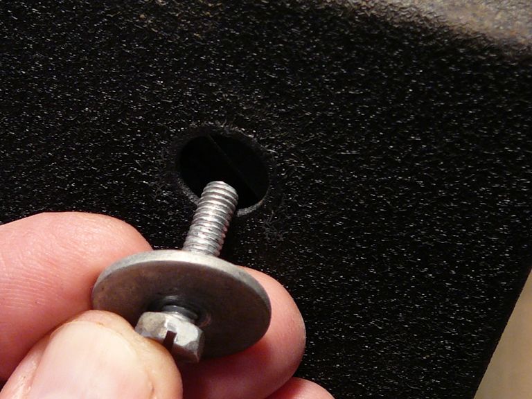 Large washers go on both sides of the hole, so clearly some sliding back & forth was contemplated. With all three screws loosened, you can slide the mirror a bit in any direction. Not foreseeing that alignment would be an issue, I have no record of exactly how it was mounted before I removed the mirrors. Nor do I know exactly where it was mounted when it produced the most recent picture, since I didn't know the screws had any leeway until I had loosened them all today. I don't have a factory jig for aligning all this stuff, so unless someone has a better idea, I'll mark the box with tape tags showing the center of each mounting hole, and try to remount the mirror dead center in all three holes. Also on my to-do list is checking the angle of the plane mirror to make sure it's exactly 45 degrees, and to ensure that each of the three side clamps is holding it the same distance from the struts (i.e., even if it's lying back exactly 45 degrees, it's not tilting sideways, either). Phil Nelson Phil's Old Radios http://antiqueradio.org/index.html 
|
|
#48
08-11-2017, 10:41 AM
|
||||
|
||||
|
You need one of these!
http://www.earlytelevision.org/philips_test.html Perhaps something similar could be fabricated.  jr
|
|
#49
08-11-2017, 11:52 PM
|
||||
|
||||
|
Wow, that Philips gizmo is clever. It sure would simplify the optical adjustment process, although fabricating one goes far beyond my pay grade.
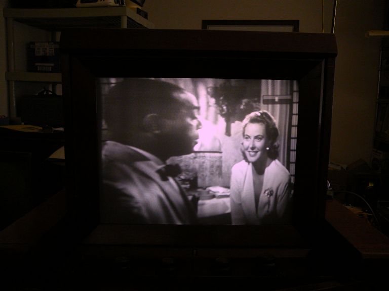
Meanwhile, I reopened the optical box today. After much fussing & cussing, I readjusted the spherical and 45-degree plane mirrors. Now, the picture is similar to what it was before I pulled those mirrors for resilvering:  I haven't yet done ANY of the multiple mechanical adjustments, so the picture is blurry and the screen geometry isn't perfect. Presumably things can be improved somewhat that way. It also looks a little bloomy on high-contrast content, as you can see in the animated .GIF. Poor HV regulation? There's no quick/easy way to measure the HV output, as you would in a conventional TV, so this is only a guess. Speaking of mirrors, I stuck my head up inside the pop-up canopy to inspect the big (final) mirror. Guess what -- it looks bad, similar to the degraded surface on the 45-degree plane mirror. That would explain some of the image weirdness seen in the last photo, which is more than just being out of focus. Tomorrow . . . . Phil Nelson Phil's Old Radios http://antiqueradio.org/index.html Last edited by Phil Nelson; 08-12-2017 at 12:04 AM.
|
|
#50
08-12-2017, 12:53 AM
|
||||
|
||||
|
I may be wrong, but I think that the vertical keystone can be improved by a side to side adjustment of the 45 degree mirror. I would not assume that the 45 degree rails are perfect.
The focus looks fairly uniform, I suspect that moving the CRT foreward or backward will sharpen it quite a bit... perhaps put a dab of lubricant on each of the 3 "fingers" that move the CRT mount so the focus action is smooth. jr
|
| Audiokarma |
|
#51
08-12-2017, 10:58 PM
|
||||
|
||||
|
Yah, I'm probably not done messing with that plane mirror.
Looking up top, I noticed that the screen's wooden frame is slightly cracked open on one side; thus, that corner of the frame doesn't slide forward all the way when you lock the screen in viewing position. Which means the big mirror is also misaligned. Note the gap on the right side, between the screen frame and the control panel frame: 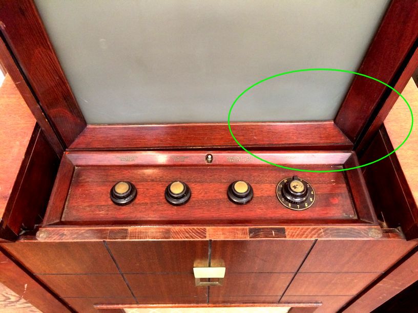 I guess these things happen when a fragile, heavy cabinet is trundled around from house to house over the decades :-( I was planning to remove the canopy anyway, to give the big mirror a close inspection. Now I have two reasons to remove it! Regards, Phil Nelson Phil's Old Radios http://antiqueradio.org/index.html
|
|
#52
08-13-2017, 04:06 PM
|
||||
|
||||
|
Quote:
Apply some sort of pattern to the face of the tube, transfer letters, decal, felt tip pen, whatever you have handy. 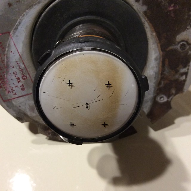 Install tube in the box and illuminate face with bright flashlight. Fenix MC-10 shown here. 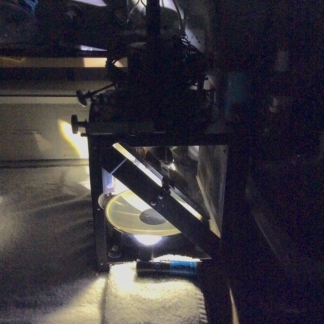 View on screen approximately 31 inches from the corrector plate... Align for best image. 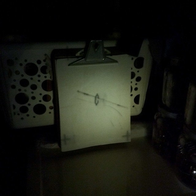 Of course, the set up could be much better, but this was just a quick n dirty experiment to illustrate the concept, using a washing machine instead of a flat level table as an "optical bench" and a clipboard with white piece of paper instead of a proper screen. jr
|
|
#53
08-13-2017, 07:29 PM
|
|||
|
|||
|
Phil you are da man when it comes to MacGyvering.

|
|
#54
08-13-2017, 09:52 PM
|
||||
|
||||
|
Yeah, something like that flashlight setup might work for aligning the optical box mirrors.
Meanwhile, I managed to extract the canopy with its final mirror & screen. (Hint: this process is a pain; don't do it without a good reason.) 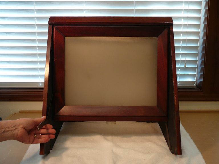 The final mirror doesn't look that bad from a distance: 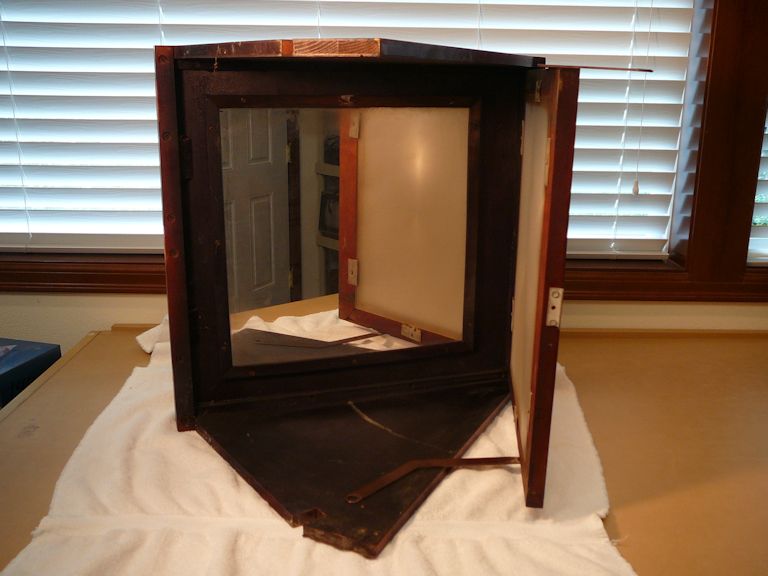 The closer you get, the worse it looks, showing the same flaws as the 45-degree mirror in the optical box. This isn't dirt; I cleaned the mirror, with no change in the degraded areas: 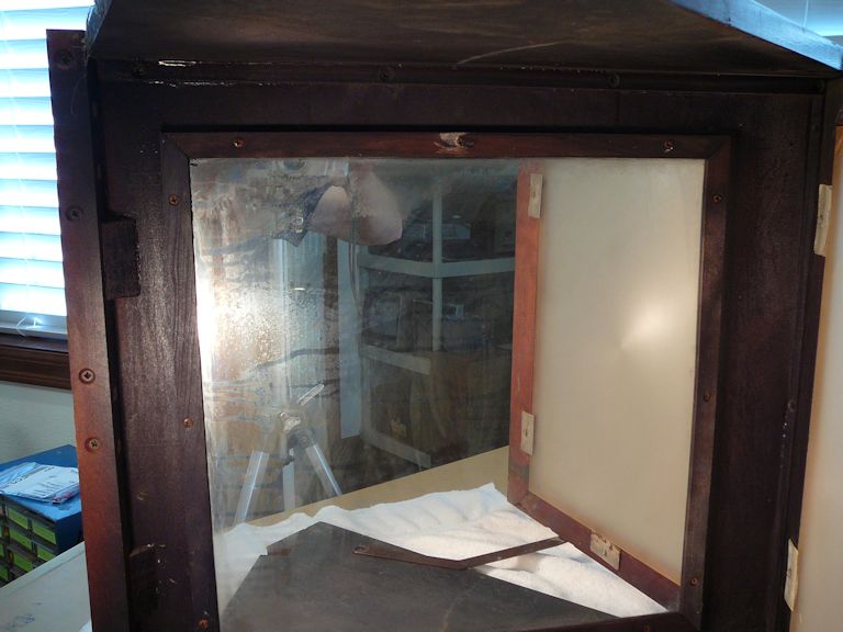 Yes, this frame corner has popped loose (and so has the adjacent one). This rail would fall out completely if the screen mount wasn't holding it from behind: 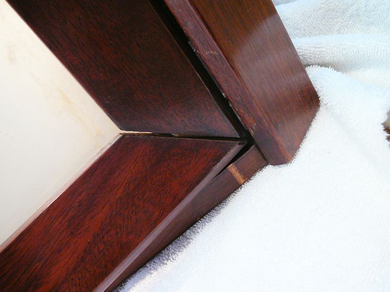 I'll pull the mirror from the canopy and send it off for recoating. That will take about a month, and during that time I can do cabinet refinishing & repair (it also has a broken leg). Maybe some MacGyver experiments, too! Phil Nelson Phil's Old Radios https://antiqueradio.org/index.html
|
|
#55
08-13-2017, 10:27 PM
|
|||
|
|||
|
Hang in there. If anybody can get this thing right you'll be the one.
|
| Audiokarma |
|
#56
08-13-2017, 11:44 PM
|
||||
|
||||
|
Thanks for the encouragement. I bought this set thinking that a projection TV might be an interesting new challenge. I got that wish, and then some!
Phil Nelson
|
|
#57
04-24-2018, 12:45 AM
|
||||
|
||||
|
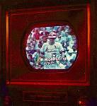
I have been puttering along with this set in recent months. After recoating two mirrors and spending more time with the electronics, it makes a better semblance of a picture:
 As you probably noticed by Sam's stretched head in that pic, the horizontal linearity is pretty awful. This test pattern shows that the vertical linearity is also poor: 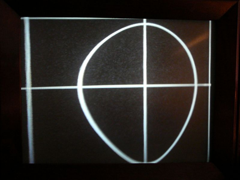 I have gone back through the sweep circuits, replacing a handful of components, without finding an obvious cause for bad linearity in both directions. If you go back to page 1 of this thread, you'll see that I removed a one-capacitor modification made by a previous owner: that cap paralleled the width coil and the idea seems to have been to affect the width. Now I'm tempted to reinstall a cap in that position and see what happens . . . . If I can't solve the linearity problem with the electronics, I'm back to fiddling with the optics, which I honestly don't understand very well. One idea that occurred to me is that maybe I reinstalled the recoated spherical mirror off-kilter. Testing that theory would be difficult, since that mirror's mounting screws are not intended as adjusters. There's a lot of elbow room for the screws in those holes and absolutely no guide as to what is the correct position. In the factory, I supose they set this mirror using a jig. I've been updating my restoration article as I go along. You can read more details and see more pics at: https://antiqueradio.org/Emerson609P...Television.htm . Regards, Phil Nelson Phil's Old Radios https://antiqueradio.org/index.html
|
|
#58
04-24-2018, 07:36 AM
|
|||
|
|||
|
Quote:
Sorry if I am asking the obvious. I really want this to be another success for you!
|
|
#59
04-24-2018, 10:48 AM
|
||||
|
||||
|
Hard to believe the optics could do all that. Maybe some combo of scan and optics, but I really think scan is most likely the cause of it all.
With all that distortion at 6 o'clock and 9 o'clock, you'd think the range of 7-8 o'clock would be worse yet if it were optics.
|
|
#60
04-24-2018, 12:23 PM
|
||||
|
||||
|
Quote:
 But if you remove the entire tailpiece assembly, you could view the CRT face fully: 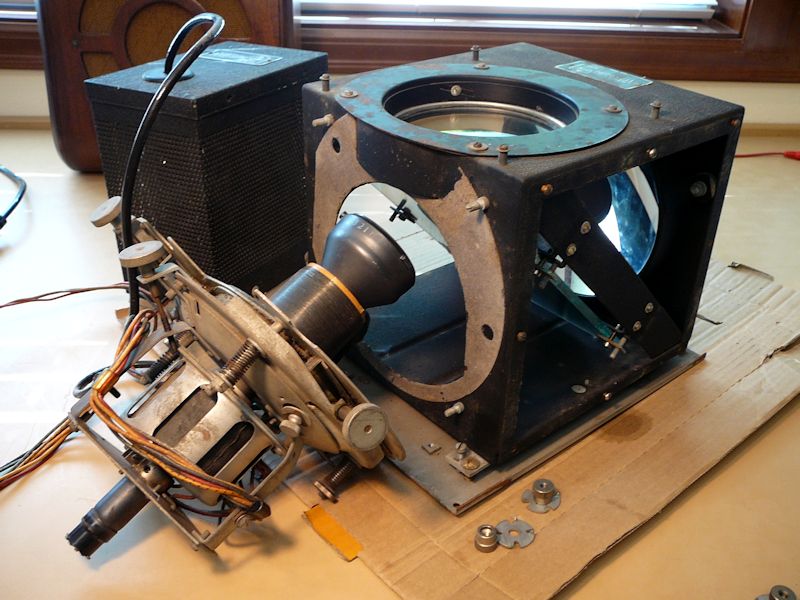 I'm concerned about X-rays in that scenario. At 25KV, X-rays are a factor, so would you get fried if you view the CRT outside the metal box? Somewhere, I saw a statement from bandersen that more X-rays are generated from HV rectifier tubes than the CRT itself. Can anyone verify that? In this set, the HV rectifiers are sealed in their own little metal box, so if the CRT itself isn't a big emitter, maybe viewing it outside its box wouldn't be so dangerous . . . ? Phil Nelson Phil's Old Radios https://antiqueradio.org/index.html
|
| Audiokarma |
 |
|
|


 Linear Mode

